Series: All Victron RV Electrical
This series covers our build of an all Victron electrical system. Take what is helpful and leave the rest—build your system for your own needs. Cheers!
Note: We are not sponsored by Victron, but we are Amazon and Tnutz affiliates.
Part 4: Wiring and Configuration
Part 5: (Future Blog Post) Alternator Charging
Introduction
In the last post I discussed my plan for the system and thought process for the “big decisions”:
- vendor (Victron)
- system voltage (24V)
- bank size (5.12kWh)
- inverter size (2400W/3000VA)
- charging method (alternator)
In this post I go into more detail on specific components and how I planned to wire, use, and arrange them.
Electrical Design
The diagram below shows the major electrical components with the exception of the Cerbo GX discussed later on.
On the left is the Victron Smart Lithium 24V (5.12 kWh) battery we purchased. I discussed this choice in the last post—it is double the energy storage we have in our travel trailer for nearly the same cost.
I used 2/0 cable for high current DC runs. It is rated for 200A continuous for the lengths required and sufficient to handle expected loads.
Battery positive connects to a 300A class T catastrophic fuse. These have an Amperage Interrupt Current (AIC) of nearly 20,000 amps and are incredibly fast acting.
I designed AC wiring and circuit protection for a 30A system. This is the most common size for small to medium RVs and works well with the Multiplus we purchased.
Our travel trailer is also 30A, so several items did not need to be purchased again. These include our Progressive Dynamics 30A EMS, 30A shore power cable, 30A extension cord, and one extra 300A class T fuse. I also used leftover 10/3 cable for wiring Multiplus AC IN/AC OUT—6/3 cable for the possibility of 50A or even 75A would not be necessary.
On the AC output side of the Multiplus is the Blue Sea Main + 6 circuit breaker. We probably will not need all six, but this model was less expensive than the four breaker option. It came with three 15A breakers plus slots for three additional, and we purchased a fourth 20A breaker.
The first item connected to the Lynx Distributer is the Orion 24/12-70A DC-DC converter. It provides regulated voltage to all the 12V DC loads.
The next connection on the Lynx Distributer is to the Smart Battery Protect (SBP). In our system it is used to shed 24V loads in case battery state of charge falls below a prescribed threshold. I discuss this further in the load shedding section below. We have one 24V load connected to its output: the Dometic DZ75 fridge/freezer.
There are two schools of thought for determining which loads should be 24V. One says anything that can be should: air conditioners, fridges, water pumps, water heaters, heater controls, vent fans, or even lights. Another, the one I adhere to, says connect high current and/or long duration loads to 24V and the rest to 12V. I believe 12V is preferable for small loads because:
- conversion efficiency loss is minimal
- cost/ease of install benefit from moving down a cable size is minimal
- 12V devices are more common and easier to find
- you are more likely to have a backup 12V source (i.e. truck battery)
Between the Lynx Distributer and the Multiplus are two Orion XS 1400 DC-DC Chargers. At this time they are not available; expected release is early 2025. In a future blog post I will cover that install and why I feel the 24V version of the Orion XS was worth the wait.
Grounding
In an RV, since no physical connection to earth exists when not connected to shore power, and is further isolated by rubber tires, grounding means a connection between system negative and chassis to avoid potential differences between them.
Some folks leave their systems ungrounded. This is a mistake.
At best, electronic components are susceptible to damage from voltage spikes, especially during an electrical storm when large potential differences can exist between negative and chassis.
At worst, ground faults are not cleared—between wires or metal cases and chassis—and a human becomes part of the circuit. In addition to getting electrocuted, you wasted money on fuses and circuit breakers. Ugh!
Isolated vs. Non-Isolated
An important question to answer is whether two separate grounds need to exist isolated from one another. This matters for solar charge controllers and DC-DC chargers, which are available in isolated and non-isolated models.
If house and vehicle are effectively part of the same chassis due to physical proximity, there can exist a single, non-isolated ground shared throughout the system to simplify wiring. This is true for a van, pickup camper, or motorhome.
However, for a travel trailer or fifth wheel, there are two chassis to consider so separate, isolated grounds need to exist for each. This is true even when vehicle and trailer are connected —which is only part of the time—since the ground path is long and unreliable. Note that this is in regard to house power only. When a trailer or fifth wheel is connected to a truck, trailer lights and brake need to have a ground connection back to the truck.
Single Point of Contact
For each chassis, ground to chassis at a single point. This is necessary because ground loops can occur anytime a circuit is connected to ground at more than one point, either through an explicit connection or from a component’s metal case that makes contact with the chassis. Foremost among issues associated with ground loops is radio frequency interference (RFI), especially when an inverter is used.
To ensure a single ground point, it is recommended to include a dedicated ground bus bar in the system connected to chassis. All other grounds, negatives, and additional ground/negative bus bars connect to it.

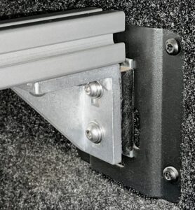
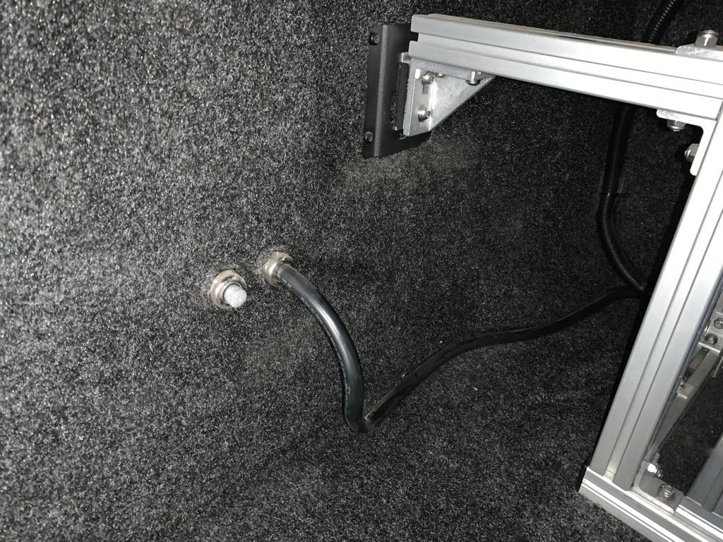
To avoid ground loops on my electrical cabinet, all electrical components are mounted to plywood and the 8020 frame is connected to ground at a single point. I used this 8020 grounding terminal. I also placed pieces of 1/4″ plywood between the 8020 frame and truck bed where the cabinet frame secures to the truck.
Placement
There is some debate where to place the chassis ground connection on the vehicle frame; the effect of factory ground straps is unclear. If you connect to thick steel frame with a solid metal to metal connection (no paint or rust), I believe you will be OK.
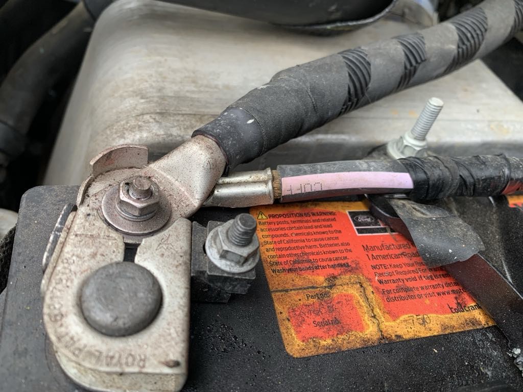
However, on my system I plan to install DC-DC chargers with up to a 100A current draw from my Ford 377A dual alternators. To take the guesswork out of the return path and minimize voltage drop, I ran 2/0 cable from driver side negative battery post to my ground bus bar. This solution covers both system ground and alternator charging cases.


Control and Monitoring
Cerbo GX
A big reason to purchase a separate control and monitoring device is because this capability is lacking in the Multiplus. Unlike most other Victron components, the Multiplus does not include built-in Bluetooth. The solutions are to either purchase a Bluetooth dongle, Cerbo GX, or one of the other communication centers. You can even build your own with a Raspberry Pi that runs the Venus OS.
For our travel trailer we purchased the dongle and that works fine for that system. With the dongle you can set input current limit and you have On/Off/Inverter Only/Charger Only control. It also displays AC input, AC output, and DC quantities.
For this build I purchased a Cerbo GX. In addition to control and monitoring capability like the dongle, it includes numerous communication and I/O ports which facilitates coordination across the system. You can even control and monitor from anywhere in the world with VRM so long as it is connected to the internet. An interesting feature is the ability to create customized screens with GUIMods to show additional quantities. I could see adding indicators for temperature, fresh water, or propane. Cool stuff!
Cerbo Display
Victron currently has two offerings for local display, the GX Touch 50 and GX Touch 70. These are nice but I decided, due to limited space, to monitor and control the Cerbo from our phones. We saved at least $200 going this route. This requires wifi configuration described in this video.
Control Circuits
The diagram below shows two circuits: on the left a temperature controlled fan, on the right a load shedding scheme. The Lynx BMS Aux port provides power to a small fuse panel with two connected loads, one of which provides power to the Cerbo. This is recommended to keep the Cerbo alive for troubleshooting in case of a low cell voltage event.
Temperature Controlled Fan
After our travel trailer build I vowed the next one would have better ventilation. When it’s hot out and we charge at high current the electrical compartment can get pretty warm.
I chose this computer fan because it was a little larger than others of this type. It is also the highest speed in this size at 3000 RPM and rated at only 5 watts.
We used the temperature probe that came with the Multiplus since it would go unused otherwise. The positive of the probe is connected to the top pin of temperature port 1, and the negative is connected to the bottom pin. The normally open side of relay 1 is connected to the fan, and the common of relay 1 is connected to the 12V fuse panel.
Configuration of the Cerbo is straightforward. From the remote console menu, go to Settings -> I/O -> Analog inputs, and turn Temperature input 1 On. Next, go to Settings -> Relay -> Function (Relay 1), and set it to Temperature. For the temperature control rules we set it to come on at 95° degrees and off at 90°.
To test it, I ran a heat gun on the temp probe to drive the temperature up to 95°, and used a piece of ice to bring it back down to 90°. Worked like a champ!
A nice feature of the Cerbo is that you can change the relay to manual mode and control the fan directly. This is done by setting Function (Relay 1) to Manual, backing out one level, and turning it on. I have done this many times when charging in warm weather.
Load Shedding with ATD Contact
The left side of the allow-to-discharge (ATD) contact on the Lynx BMS is connected to system voltage (24V) at the small fuse panel. The right side of ATD is tied to the H pin (right side) of the remote connector on the Smart Battery Protect (SBP).
To complete the configuration, one SBP setting, Mode, needs to be set to ‘C’ for Li-ion mode.
When any of the battery cells falls below 2.8V (settable in the battery) or when a discharge floor of 10% (settable in the Lynx BMS) is reached, the ATD contact opens, turning off the SBP and any connected loads. In our case our Dometic Fridge/Freezer.
This is the recommended way to connect loads for systems with an external Victron BMS. If it is the Lynx BMS, employing this circuit also adds redundancy. For example, if the above conditions are met—low cell voltage or discharge floor is reached—ATD opens. If no charge voltage is detected after 5 minutes, the Lynx BMS contactor opens and the system shuts down. Note that any Victron device having remote control pins can be tied to the ATD contact in this way.
On our system, where the fridge is the only load connected to the SBP, an important purpose is served: it is the last load shed since we want to preserve our food. If we leave for a three night backpack we turn off the Multiplus and 24/12 converter—only the fridge can draw the battery down. However, we would rather lose food than damage the battery.
Cabinet Requirements
- [Requirement] Provide sufficient ventilation for components that generate heat.
Heat is a big issue in an electrical cabinet, effecting capability and health of the system. In our cabinet the Multiplus will generate the most, especially when charging.
The Multiplus manual states “There should be a clear space of at least 10 cm (~4″) around the appliance for cooling.”
Also, since the Multiplus-II is over 21″ tall, the best place to mount it in an upright position is adjacent to the truck cab. These heat-generating Victron components are designed for optimal placement in an upright position, which allows for natural convection—hot air rises and cool air falls.
Lastly, as noted earlier I planned to install a fan in the cabinet to further help with ventilation.
- [Requirement] Provide sufficient space to torque Project M mount bolts without removing the cabinet.
There are three 3/8″ bolts on both sides of the Project M that secure it to the truck—we need access to these for occasional tightening.
- [Requirement] Provide sufficient space for transporting kayaks on local trips.
Our Hobie Itrek-11 inflatable kayaks are 10’8″ long. These need to fit inflated, one on top of the other in the Project M for local trips. We can drop the tailgate to provide additional space.
Cabinet Design
The design needs to capture and provide some validation for location and layout decisions—in a small space everything needs to have its place. Components should be easily accessible to control, monitor, charge, and use, yet protected to prevent damage.
Sketchup
For the cabinet design task I used the free web version of Sketchup. In addition to a three dimensional view, it provides exact scaling, answering the question of whether components are going to fit with space for wiring and ventilation. I like Draw.IO (it’s also free) and used it for all our diagrams on our last build and for the electrical diagrams on this build, but I feel learning Sketchup for structural design really upped my game!
If you click on the above diagram the Sketchup viewer will load after 10 seconds or so. You can zoom in and out, pan, or orbit to view it from different angles.
After the viewer loads, you can also download the full diagram by clicking the 3D Warehouse link in the lower left corner. If you open it in a Sketchup editor you can hide or show various parts with tags I created, or copy components and build your own diagram.
If you are completely new to Sketchup and want learn more about it, start here.
Diagram Description
If you use the orbit tool to view the left side of the diagram, you will see a 30A inlet for shore or generator charging, plus a 30A breaker for Multiplus AC input. It also includes a remote switch to the Lynx BMS contactor, which controls main power to the system.
If you orbit to the right side you will see the Multiplus AC output breaker panel, 3-gang switch panel, and remote switches for the Multiplus and 24/12 converter.
Both sides include two GFCI outlets separated by a 12V outlet.
I began by taking measurements in the Project M: shelf height, distance between shelves, height of backwall below bed platform, and so on.
Our initial plan was to keep the back window clear so we could see while driving. However, we decided camping gear would block the view. This cleared the way to use full backwall height to the bed, minus a few inches for ventilation.
The final design is a simple rectangular frame 45″ tall by 45 7/8″ wide, fit snuggly between the side shelves against the cab. Frame depth was determined by where the front supports mounted to the Ford Boxlinks, which was 14″ deep.
The frame itself will be built out of 15 series (1.5″ x 1.5″) 8020 aluminum and is discussed in the next post.
For placement of components inside the cabinet, I recorded measurements for all major components and found their best likenesses in the Sketchup 3D warehouse, then resized to actual dimensions. If I could not find a good component match, for example the battery, I built a simple rectangular solid of the correct dimensions. I also added color and/or material surfaces as needed.
It was not my intention to win an art contest; rather, I used the diagram as a starting point to get a sense of how it all would fit together. I did find a truck that looks just like ours, only it was a short box. I resized the bed to 8 feet and I was good to go!
Next Up
In the next post the system literally begins to take shape—literally used correctly here—as I discuss how the electrical cabinet was constructed.
Parts List
Here is a list of items we purchased to build our system.
You can navigate the Excel spreadsheet below directly or download the file through the download button on the bottom right.
We are Amazon affiliates and appreciate your purchases through the provided links.
We are also Tnutz affiliates. They offer the lowest prices on the web for aluminum extrusions, brackets, and much else. Before ordering through Tnutz check out this page to learn how to save on shipping.
Thank you!