Series: All Victron RV Electrical
This series covers our build of an all Victron electrical system. Take what is helpful and leave the rest—build your system for your own needs. Cheers!
Note: We are not sponsored by Victron, but we are Amazon and Tnutz affiliates.
Part 4: Wiring and Configuration
Part 5: (Future Blog Post) Alternator Charging
Introduction
In the last post I covered design of the system, both electrical and structural. In this post I step through cabinet construction: frame, panels, fasteners, assembly, plus additional component layout decisions.
8020 Extruded Aluminum Frame
As discussed in the first post of this series, we ordered a Ford Transit and planned to do our own campervan buildout. After we cancelled that order and purchased the Project M, I still wanted to do some of those things. At the top of the list was to build something out of 8020 aluminum.
“8020” is a brand, but it is most often used as a generic term for T-slotted extruded aluminum.
I read on the van forums about folks using 8020 to build strong and light frames for their conversion: floor, walls, ceiling, bed, electrical, plumbing, and everything cabinetry. A big advantage of 8020 over wood cabinetry is that the tools and skills required to get started are minimal. Also, it is easy to reconfigure as needs change; it’s an erector set for adults!
My “Hello World” program—first attempt—with 8020 was the frame for this power system. I planned to use this project to figure out what works and scales well for a more involved future van build.
Series
The first major decision is extrusion series or size in either fractional or metric. I chose 15 series, based largely on this DIY website and advice offered on van forums by a fellow named Orton. He built his own van conversions with 15 series and shares many keen insights. Other than a few exceptions I followed his example.
Much of the debate between fractional 15 series (1.5″) or 10 series (1″), or some metric size in between, centers on space/weight/cost savings if a size smaller than 15 series is used. However, many argue the more important factor is strength of 5/16″-18 fasteners used with 15 series vs. 1/4″-20 for 10 series. It is reported that 1/4″-20 carriage bolts do not fit as well in 10 series and these bolts can break easily when tightened.
I believe thoughtful design choices can mitigate downsides of the larger, heavier 15 series. For example, using the lightest 15 series, 1515L instead of1515. Or, using aluminum flat bar rather than extrusions where possible.
We purchased all four slotted EX-1515L extrusions. I considered other slot counts, but decided four slots would provide the greatest flexibility for making changes.
Connector Type
The second major decision is type of connector, internal or external. Internal connectors are recessed into slots and considered more aesthetically pleasing. However, in most cases the extrusions require additional machining costs. This is a good choice for commercial products.
External connectors reside on the surface of slots and are more accessible for making changes. I went this route, and as Orton recommends I cut corner brackets myself from angle aluminum stock. This was a part cost, part curiosity decision. The cost savings was clear; unknown was how tedious it would be to make the brackets. I can now say this task provided copious amounts of alone time with miter saw and drill press, which is priceless.
Vendor
Vendor is another important decision, especially if keeping costs down is one of your goals. I would have considered a local vendor, but none were available in my area.
We ended up purchasing all our extrusions from tnutz.com. There are multiple extruded aluminum vendors online, including 8020.net, but Tnutz had the best prices. They do not have the variety of extrusions, connectors, and accessories that 8020.net offers, but they have plenty of what you need.
Cutting
I spent some time thinking about the best way to cut the extrusions. I considered metal cutting saws, but ended up purchasing a Dewalt 12″ miter saw. Miter saws are a good choice for both aluminum and wood.
I also built a stand similar to this one and rigged up our shop vac to catch aluminum shavings.
I purchased a D1296N Diablo 12″ 96 Tooth Non-Ferrous saw blade to cut all the aluminum. This blade worked flawlessly. In between cuts I used WD-40 on the blade for lubrication and an air compressor to blow off the work surface.


Drilling
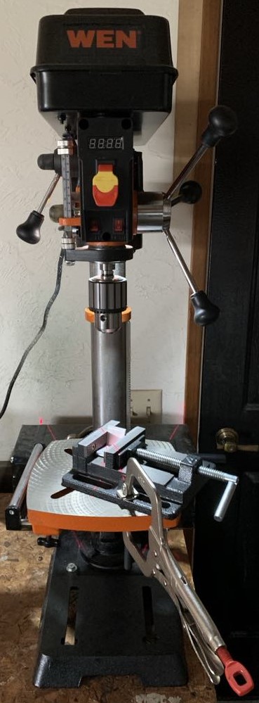
DIY brackets require lots of drilling. For this I purchased a Wen 4214T 12-Inch Benchtop Drill Press, Bessey BV-DP40 4-in Drill Press Vice, and two sets of Milwaukee 11″ Torque Lock Locking C-Clamp pliers.
I wanted a drill press for a long time and am pleased with functionality and ease of use of this one. My favorite features are the variable speed adjustment with digital speed display (no belts to move) and laser sights. These features alone make it a great value. Similar to cutting, I used WD-40 for lubrication when drilling aluminum.
Corner Brackets
To support the frame, I cut corner brackets from 1 1/2″ x 1 1/2″ x 3/16″ angle aluminum stock.
For panel mount faces I used Orton’s “B” connector to inset approximately 1/8″, otherwise I used Orton’s “A” connector. They are fastened with stainless steel 5/16″-18 x 3/4″ carriage bolts.
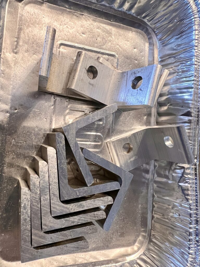
During initial construction I used regular hex nuts to make it easy to disassemble and reassemble. To finalize assembly, I applied anti-seize to bolt threads and replaced them with nylon lock nuts.
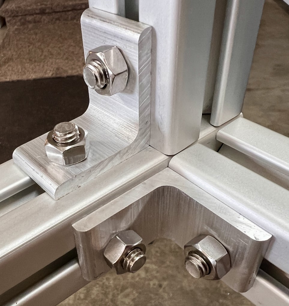
There are eight corners on the frame with three brackets per corner. Three brackets are required in each corner because each extrusion requires two brackets to be fully cantilevered at 90°.
Assembly
Once the extrusions and brackets are cut and drilled, its time to connect them together. This requires more thought than you would expect. Once extrusions are fastened, some slots are no longer accessible—they are “captivated” or blocked by adjacent extrusions.
I also found it was easy to confuse the order to place items into slots, or which slot was which as the frame was rotated and flipped.
I created the spreadsheet below where I identified extrusion faces and associated fasteners.
I went through the spreadsheet several times to root out items I had overlooked. Once satisfied, I labelled extrusion faces that would include fasteners, each identified by spreadsheet row number, plane, position, and face. I then used the spreadsheet as a guide to load the slots with the correct number, order, and type of fastener. Regardless of how you do it, at this stage it helps to be methodical in your approach.


Fastening to Truck
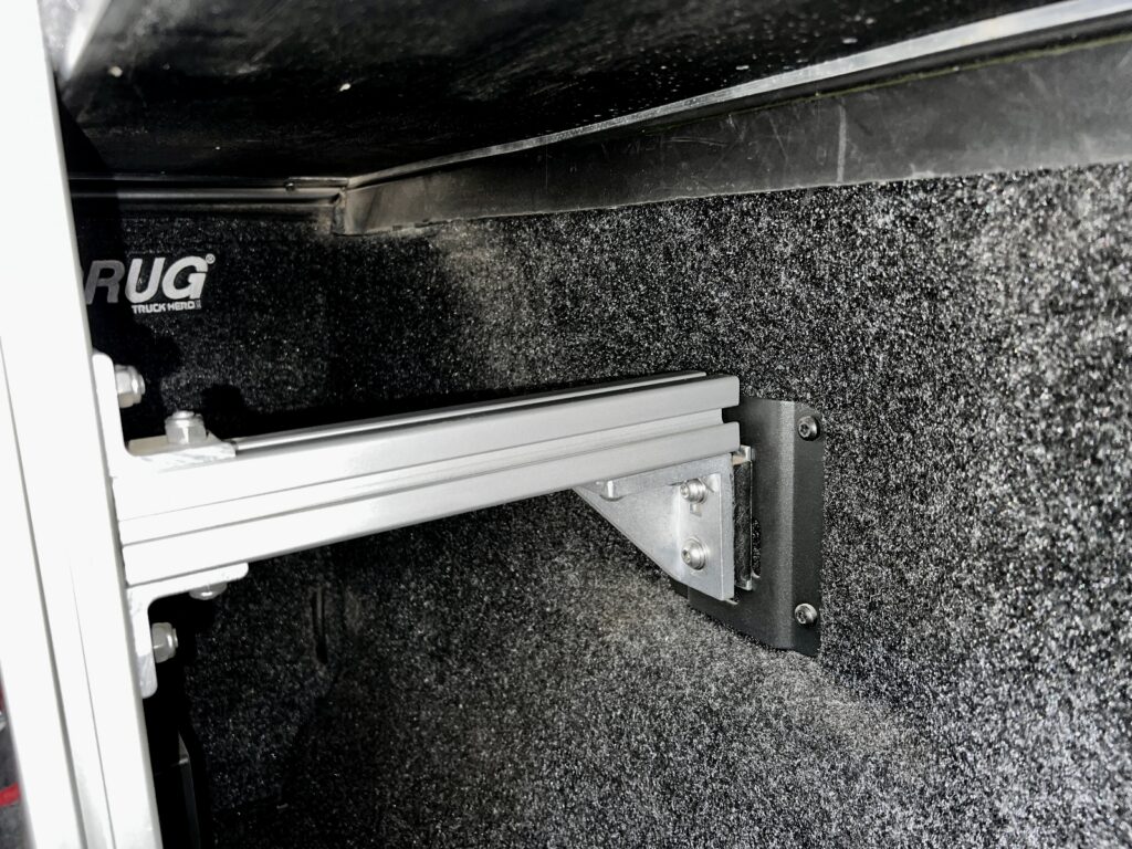
I found these HandETrack anchors to secure the frame to the bed BoxLinks. Each HandETrack has two 5/16″-18 bolt holes. I purchased 8020 inside corner brackets (part #14081) to connect the HandETrack to extrusions mounted flush to the frame. I also inserted a small piece of 1/4″ plywood (painted black) between the HandETrack and the bracket to act as both an insulator and a spacer between the bracket tits.
Panels
Once the 8020 frame was built, next up were the panels.
Back
For the back panel where heavy, heat producing components reside, I briefly considered aluminum sheet and/or flat bar, especially for the Multiplus. However, to minimize the possibility of ground loops I decided on 3/4″ plywood. This thickness works well for fastening heavy components.
I split the back panel into two pieces to make them easier to handle. The panel on the right supports the Multiplus and the panel on the left spans the full length of the battery. This was handy during early stages of construction. I also thought it would be easier to lift the cabinet into the Project M with back panels removed, but decided to remove just the battery and Multiplus to minimize rewiring.
Sides and Top
For the sides and top lid there were several possibilities in 1/4″ thickness. ABS plastic is attractive, strong, and does not require finishing. However, it is expensive and large 4′ x 8′ sheets require shipping since it is not available locally. Other common materials include PVC and HDPE, but these are also expensive and not readily available. Another option was melamine coated MDF, it is cheap and does not require finishing, but I felt it would not hold up in damp environments.
I decided on birch 1/4″ plywood. It was cheap at $45 for a 4’x8′ sheet, strong, light, handles moisture and heat well, and is quite thin (0.188″ actual thickness)—it would inset nicely into the frame. It made sense on this first project to start with the least expensive and move up (if necessary) in price on a future build. This thickness required a “strongback” centered along the length of the side panels to increase rigidity for outlets. For this I used 3/4″ x 3/4″ square dowel glued with liquid nails.
Front
For the front panel I went with clear polycarbonate sheet, a.k.a lexan. This material is over 200 times stronger than glass and does not crack as easily as clear acrylic (plexiglass). A clear front allows for visual inspection of the cabinet, view of indicator lights, and looks really cool! We also installed a red LED strip behind the lexan—handy for when I use the Porta Potti in the middle of the night.
The 48″ x 48″ lexan I purchased is quite thin (5/64″) and has a lot of flex to it. In addition to the panel brackets discussed later on, I secured the top corners of the lexan to the frame brackets with small strips of 3M Dual Lock to keep them from flaring out. I am fine with this solution because thicker pieces were quite a bit more expensive, but you may want to go a size thicker for your lexan.
Cutting
To cut the panels I purchased a Makita 6 1/2″ Track Saw with stackable case, two 55″ guide rails, two clamps, and guide rail bag. This is a big purchase for a DIY project, but I found a complete, lightly used set locally for $450. Worth it.
In the past I struggled to make straight cuts on sheet lumber using a circular saw. With the track saw I can make clean and precise cuts with little difficulty. I set the saw to score depth on the first pass, then made a final cut on the second. Piece of cake! I also used it to cut the front lexan—no score cut needed.
Another timely purchase was a Milwaukee Multitool. It enabled me to quickly make plunge cuts into panels for outlets, breakers, switches, and vents. The alternative would have been to drill holes and use jig saw; a slow and cumbersome process.
Fastening to Frame
Back
I used these panel retainers to fasten the two back panels to the frame, four on each. They are sturdy and allow for a 1/8″ inset of 3/4″ plywood. For the panels to sit flush against the retainers, two rabbet cuts in each corner are necessary to allow space for frame bracket and bolts. I used my track saw for this but a router would have been better. Next time.
Sides and Front
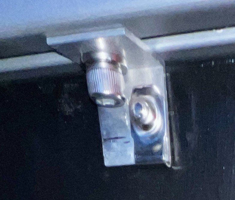
To secure the sides and front, I cut 1″ brackets from 1″ x 1″ x 1/16″ angle aluminum stock. Each panel is fastened to four centered brackets and is supported in the corners by the frame brackets. Following Orton’s “I” connector method, I used 5/16″-18 double economy nuts to secure the brackets to the frame, and used a set screw on one side to hold it in place. I used #10 clip nuts to secure the panels to the brackets.
Top
To fasten the top lid I purchased this magnetic latch kit, hinges, and cabinet handle. One side of the latch has a stronger magnet than the other, so I used the stronger side to ensure the lid stays shut on rough roads. I also glued a thick black oxide 3/8″ steel washer to the lid to attract the magnet since the included hardware was incompatible.
Lessons Learned: 1/4″ Plywood
In certain cases the 1/4″ plywood panels did not sit flush in the corners. When that happened I glued on leftover lexan to act as a spacer.
The are two reasons why this occurred:
- panel brackets did not sit back far enough and even with the frame brackets, and
- the thin plywood flexed and warped over the long span.
To get all the brackets to align evenly along the panel face, either the frame bracket holes needed to be offset less, or the panel brackets fastened further back. I do not want to give up the 1/8″ inset that the current frame bracket hole offset allows. For the panel brackets, perhaps 1/4″-20 double economy nuts rather than 5/16″-18 may have helped since smaller bolt heads would have allowed them to sit back further.
There is plenty to consider for the next 8020 project, which is a big reason for doing this one. I may decide to use a different panel material and/or method of fastening. Regardless, I expect to do plenty of additional research before next time rolls around.
DIY Bus Bars
Another new-to-me thing was DIY bus bars. Bus bars allow components to fit closer together than would otherwise be possible with cables and terminals. You can buy pre-built bus bars, but sizes are limited and they are somewhat expensive.
I only used two small bus bars, one on either side of the red main disconnect switch. This provided additional space between the Lynx Distributer and Multiplus to meet the 4″ minimum for heat dissipation around the latter.
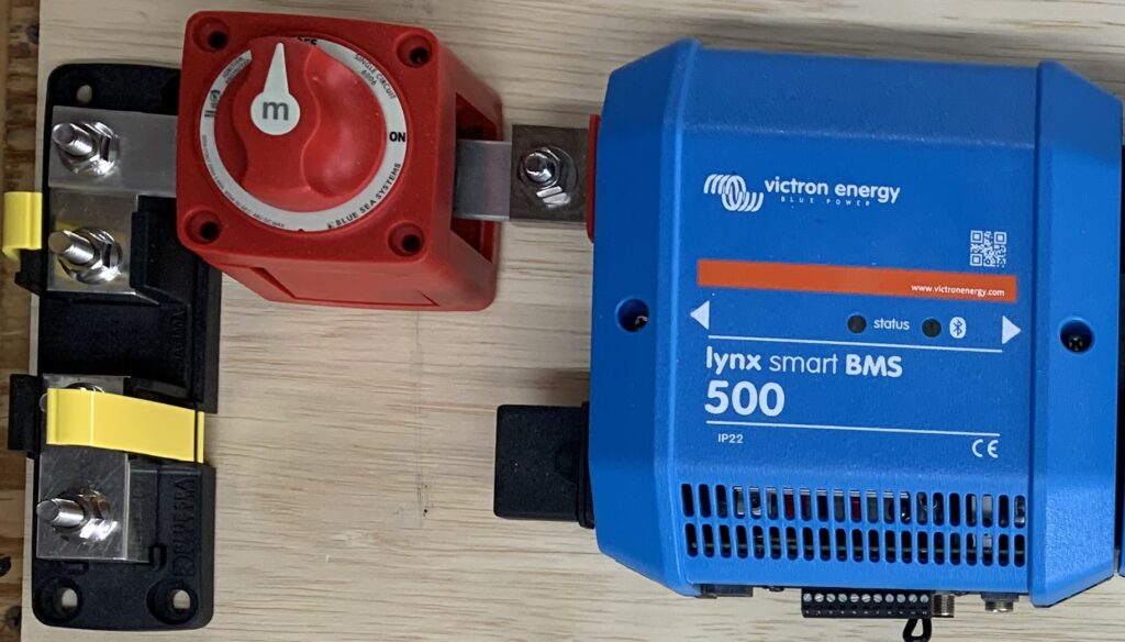
I purchased 1″ x 1/8″ tinned copper bus bars, which have a 275 amp rating for 40°C ambient temperature with a 30°C temperature rise, which is much hotter than should ever occur. They should stay cool below 200 amps—rarely should we hit even 100 amps on this 24V system. Mine are very short and uninsulated, ensuring rated ampacity will not be impacted.
I cut the bus bars in the same manner as aluminum with miter saw, Diablo non-ferrous cutting blade, and WD-40 as lubricant.
I upped my game a bit for drilling—copper is grabbier than aluminum. For lubrication I used tap magic cutting fluid. First I drilled small pilot holes, then slowed drill speed and used a brand new bit for clearance holes. I also applied less pressure and took more time drilling.
A common issue for bus bars is getting components to lay flat. This is not a problem for cables because they bend easily when fastened. To deal with this I added a 1/4″ plywood spacer behind the disconnect switch to level out the connection to the class T fuse holder. On the other side the bus bar is connected to the back (rather than top) side of the Lynx BMS connector, which allowed that connection to sit flush as well.
Component Layout
After months of research, planning, design, and now constructing the cabinet, there came a point where the metal met the meat. How do I put all this crap together and make it work?
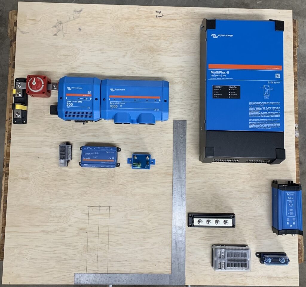
The picture below captures this period. I laid the back panel on a table and arranged major electrical components based on the Sketchup diagram. There was plenty to think about.
Where do I run cables and wires to avoid a rat’s nest?
On our travel trailer there was less to consider since it was an existing system. A large portion of the wiring was already in place: power inlet, circuit breakers, fuse panel, and outlets. With the exception of two 12V circuits for lights and Maxx fan on the Project M, this would be a standalone system.
I laid out the components and rearranged them. New ideas appeared and I created updated Sketchup diagrams. At one point I laid out the Lynx BMS and Distributer vertically. Space was added in some ways and limited in others.
I eventually settled on the layout shown above. The right side of the square corresponds to the right edge of the battery where the two pieces of plywood would be cut in half.
The two faint rectangles penciled in on the left side of the square show where a notch was cut. This provided space behind the battery for the tie down bracket fastened with 11″ carriage bolts. I also cut a notch below the DC fuse panel on the right for cables and wires to run behind the cabinet.
A major consideration was where to run cable and wire from the left side of the system to the right. This includes cables for the Multiplus, AC outlets, DC outlet, plus some others. My solution was to install a plastic cable raceway above the battery. I had seen these used in other installations and thought they looked pretty snazzy.
Another factor effecting layout are the two built-in communication cables on the left side of the battery. These need to connect to the Lynx BMS. You can purchases extensions in lengths of one meter or longer, but I didn’t want all that extra cable. So, I positioned the battery and BMS within reach of each other.
The sides also needed space for wiring and space to separate those components from those on the back panel. For example, approximately 4″ between the right side of the Multiplus and the wiring behind the AC output circuit breakers. One thing that helped was using these shallow outlet boxes.
Next Up
In the next post I discuss wiring and final configuration of the system. There is also a big photo dump at the end worth checking out.
Parts List
Here is a list of items we purchased to build our system.
You can navigate the Excel spreadsheet below directly or download the file through the download button on the bottom right.
We are Amazon affiliates and appreciate your purchases through the provided links.
We are also Tnutz affiliates. They offer the lowest prices on the web for aluminum extrusions, brackets, and much else. Before ordering through Tnutz check out this page to learn how to save on shipping.
Thank you!