Series: All Victron RV Electrical
This series covers our build of an all Victron electrical system. Take what is helpful and leave the rest—build your system for your own needs. Cheers!
Note: We are not sponsored by Victron, but we are Amazon and Tnutz affiliates.
Part 4: Wiring and Configuration
Part 5: Orion XS 1400 – Concept
Part 6: Orion XS 1400 – Design
Part 7: Orion XS 1400 – Installation
Introduction
In the last post I went through the process of building the electrical cabinet. In this post I cover wiring through final configuration, and end with a big photo dump of the system.
Big DC Cables
Major components are mounted and back panels are installed—time to run the big fat cable. I’ve got my electrical diagram, cutters, terminals, and heat shrink all set to go. I know where everything goes because I’ve thought it to death. Where to start?
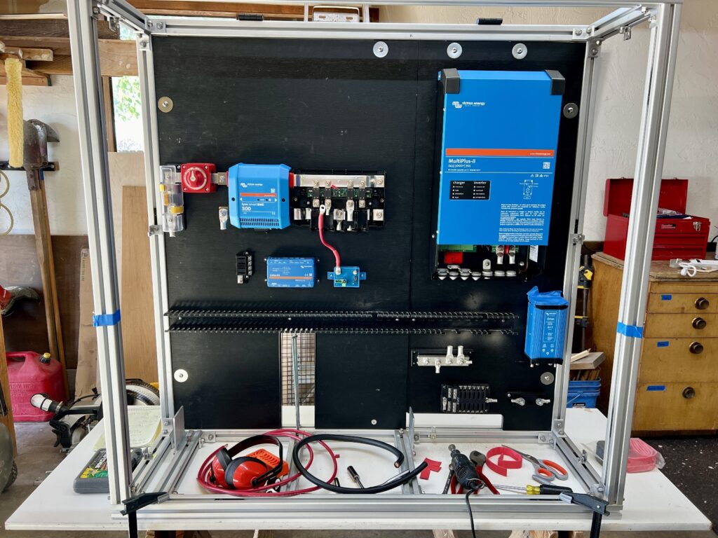
If I crossed wires at this point things would get ugly fast, so I created and followed this procedure:
- 6 AWG red from 24/12 converter input to Lynx Distributer position #1.
- 6 AWG red from SBP input to Lynx Distributer position #2.
- 6 AWG red from 24/12 converter output to Mega fuse holder.
- 6 AWG red from Mega fuse holder to 12V fuse panel positive.
- 2 AWG black from 8020 ground to ground bus position #2.
- 6 AWG black from fuse panel negative to ground bus position #1.
- 2/0 black from ground bus position #3 to Lynx Distributer ground.
- 2/0 black from Multiplus ground to ground bus position #4.
- 6 AWG black from 24/12 converter ground to ground bus position #4.
- 2/0 black from Multiplus negative to Lynx Distributer position #3.
- 2/0 red from Multiplus positive to Lynx Distributer position #3.
- 2/0 red from battery positive to class T fuse.
- 2/0 black from battery negative to Lynx BMS negative.
The pictures below show the cabinet after DC cable had been installed. Not shown is the 2/0 cable ran from truck battery negative to ground bus position #1.


It’s important to use a good hydraulic crimper for making these connections. I also use Ideal Noalox anti-oxidant compound on all high current cable ends prior to crimping. Noalox literature says it promotes cooler operation and longer connection life. I’m good with that.
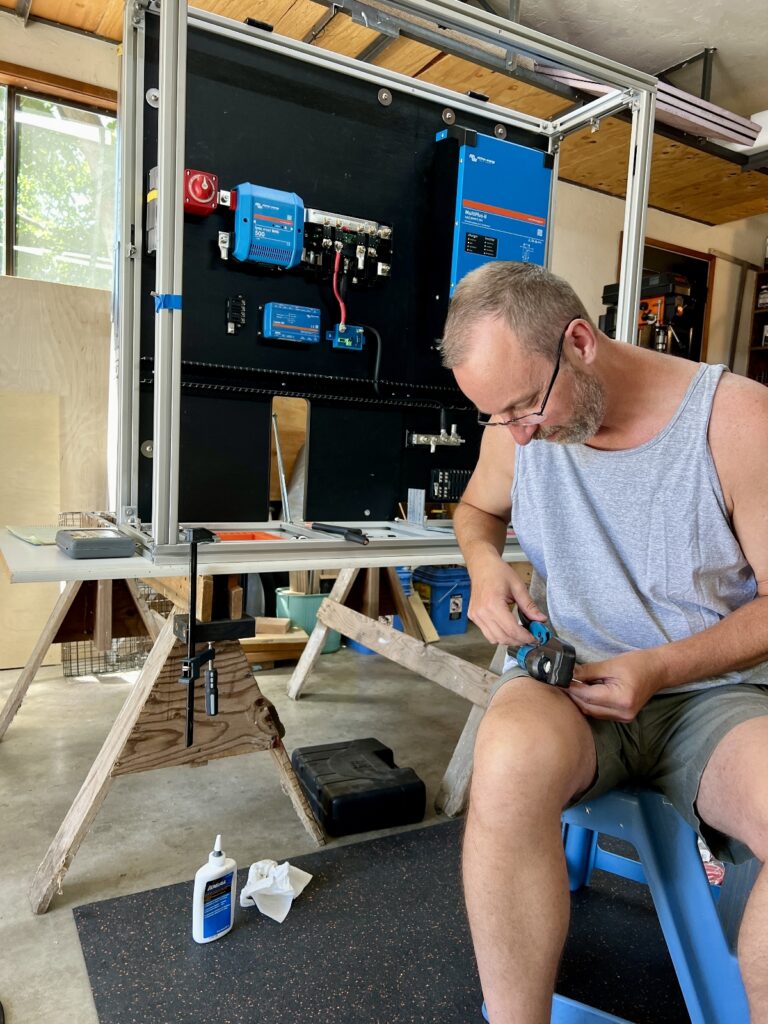
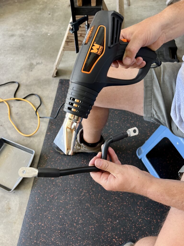
I used heat shrink with glue to finalize all connections.
AC Wiring
30 AMP
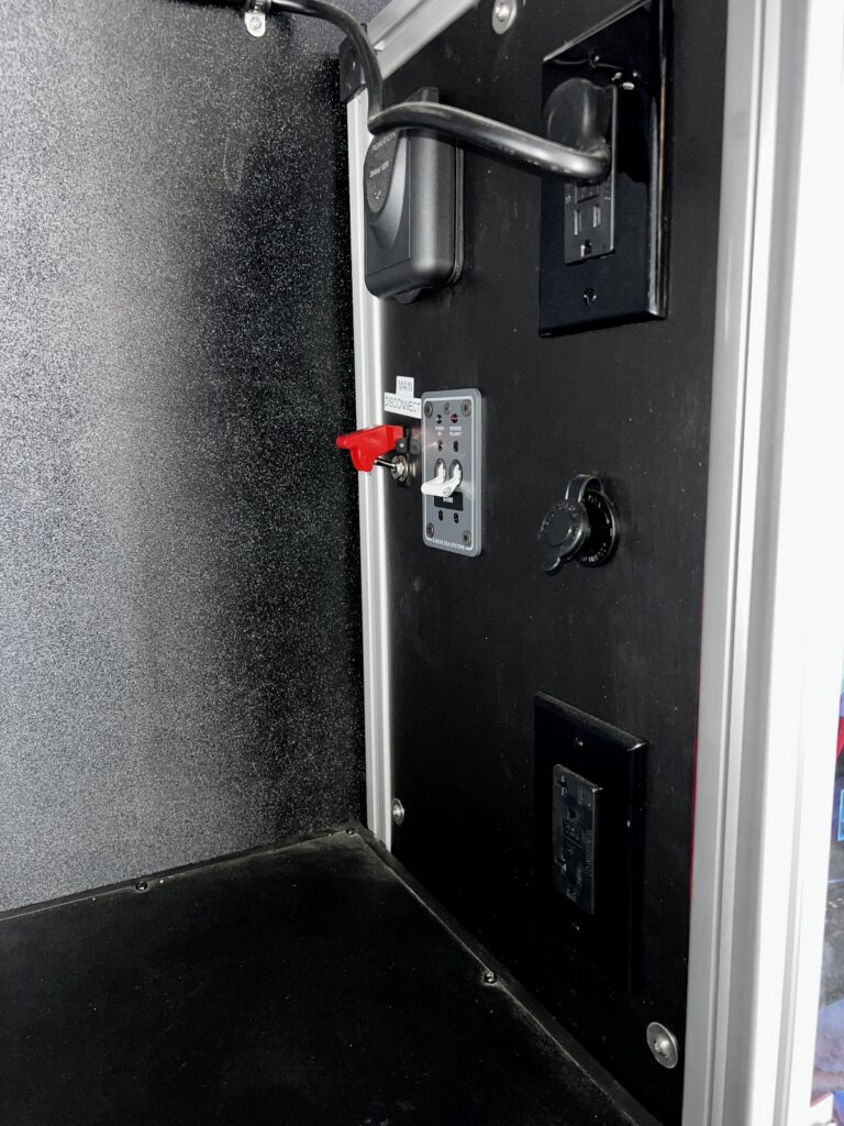
In my design post I explained why I made it a 30A system. Here I discuss implementation starting with the 30A inlet. I placed the inlet on the left (driver) side, adjacent to the emergency exit window for access. I used leftover 10/3 SOOW cable to run from the 30A inlet, through the 30A main breaker, into and out of the Multiplus and into the 30A main +6 breaker. I recommend flat, tinned marine grade 10/3 cable over the SOOW cable I used; SOOW is bulky and does not bend or hold form as well.
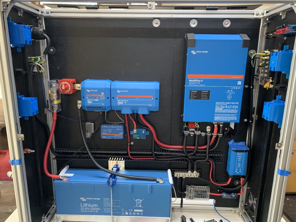
Multiplus-II Spring Loaded Terminals
One of the trickier parts of the entire build was securing 10/3 cable into AC IN and AC OUT on the Multiplus. A major change for the Multiplus-II was the addition of spring loaded terminals. On my first attempt I was unable to retract the springs fully to insert the cables.
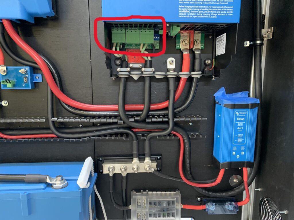
Then I discovered this Wera actuator tool. It makes inserting and removing cables into these terminals a much easier task.
To use the tool, face the Multiplus in its upright position. Insert the tip of the tool into the release tab (small hole) of the terminal. Rotate it towards you 20° or so and push it up into the hole really hard. It will slide in a half inch or so. Next, push the tool away from you. This should completely open the large hole to insert the ferruled cable. Slide the cable into the hole all the way and remove the tool. Give it a good tug to ensure the cable is tightly clamped.
Also, I could not use the insulated ferrules I had used in the past since they do not fit far enough into the terminals—non-insulated ferrules are required. Victron recommends 0.7″ or 18mm non-insulated ferrules.
GFCI Outlets
The main +6 circuit breaker we purchased came with three 15A breakers and we purchased a fourth 20A breaker. To keep things simple I wired a single GFCI outlet to each breaker. I did this because on our travel trailer we occasionally forget to put large loads on separate circuits and a breaker trips.
As with any stranded cable, I like to use ferrules or terminals for connections that would otherwise be to bare wire. However, I discovered this is not always the best approach. I had planned to attach cables to the GFCI outlets with ring connectors, however they did not fit without breaking off several bits of plastic on the outlet. This was a mistake.
I did a bit of research and discovered these outlets come with compression tabs that are designed to hold either solid or stranded wire equally well. Sometimes easiest is best. For these connections I simply inserted the stranded wire into the compression tabs and tightened them down. Done.
Small DC Wiring
For this project I set out to improve my small gauge (< 8 AWG) wiring skills. Never before had I planned this much wiring, and the last thing I wanted was electrical trouble out on the road.
Single vs. Double Crimping
I found this informative Marine How To article which fully covers marine wire termination; tools, terminals, and techniques are discussed. Of particular interest was the author’s illustrated discussion of single and double crimps.
A double crimper crimps both wire and insulation in a single action, whereas a single crimper just crimps the wire.
I decided to use single crimp heat shrink terminals exclusively. I went this route because:
- single crimps are simpler since they require fewer steps:
- strip—position terminal—crimp—shrink vs.
- cut heat shrink—insert over wire—strip—position terminal—crimp—shrink
- single crimps are less error prone. There is no right or wrong side of the crimper where you have to capture both wire and insulation, and there is more leeway in tool placement and strip length because the tool is thinner.
- I did not want to buy two crimpers!
Terminals
I followed the recommendation of the Marine How To article and tried to match tool and terminal manufacturer—I went with FTZ for both. I looked at other brands, but FTZ was the best priced. I’m impressed with the beefiness of their terminals compared to the el cheapos that are more common for the DIYer.
Naturally, the first place I looked for FTZ products was Amazon; however, their stock is limited. You can buy direct from the FTZ site, but you need an account—that I can’t seem to get—and you must buy in bulk.
Then I discovered HomElectrical. They sell FTZ terminals in small quantities at good prices; the challenge is finding them on their site. My approach was to look up part numbers on the FTZ site here, then search HomElectrical by part number for multipacks of terminals in quantities of 5 to 25. I purchased the FTZ ClearSeal terminals because this is mostly what they stock and they are reasonably priced.
In addition to a new crimper, I also upgraded my wire stripper to this one by Ideal. This tool saves time and strips with greater precision than any stripper I have owned in the past.
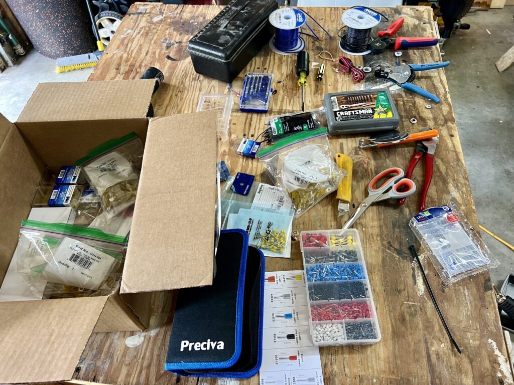
Estimates
Next, I estimated length and gauge of wire for each circuit—another spreadsheet.
Wiring
Besides estimates, the same spreadsheet can be used as a wiring procedure. This is much faster than if I were to create and follow a full wiring diagram. This spreadsheet was handy for wiring the:
- 3-gang switch panel
- power system lights (controlled by the first gang switch)
- Lynx BMS control wiring and load shedding with ATD contact
- temperature controlled fan
I used 18 AWG wire for these circuits. This is a nice size because it is small enough, with ferrules installed, to fit in Victron terminal connectors, yet large enough to handle control currents up to 5 amps. I purchased two rolls of 18 AWG, 100 foot each of black and blue wire.
Ferrules
Ferrules are a must for making reliable connections to Victron terminals. In addition to ferrules that came with this kit, I bought extra-long 12mm ferrules for 18 AWG wire. These fit better than shorter ones in certain Victron connectors.
Wago Nuts
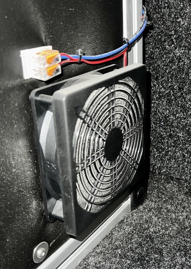
Wago nuts make fast work of small gauge wire connections, down to 22 AWG. The photo below shows how the cabinet fan connects to two stacked Wago nuts attached to the cabinet with 3M Dual Lock. If this cheap computer fan fails connecting a new one will be no problem.
Cost Savings
We saved some dollars by purchasing cable and wire in bulk, up to 100 foot rolls, and by limiting the number of different wire sizes used. For example, I planned on using 14/3 cable for the three 15A AC circuits, and 12/3 for the single 20A AC circuit. Instead, I moved the three 15A circuits up to 12/3 cable and bought a single roll for all four circuits. I did the same for Project M lights/fan/flood lights, moving those cable sizes up from 14/2 to 12/2, matching the cable size used for the Dometic DZ75 refrigerator at 24V.
By not purchasing either 14 or 16 gauge wire, I mostly omitted that range of terminals, which resulted in further savings. Most terminals purchased were either 12-10 AWG or 22-18 AWG. I did buy 16-14 to 12-10 AWG step down butt splices for converting 16 AWG lights, fan, and refrigerator wire for 12/2 runs to the power system.
Fuses and Breakers
Here is my final listing of all fuses and breakers:
30A Main Breaker Panel
- In – Furrion 30A Inlet
- Out – Multiplus AC IN
30A Main + 6 Breaker Panel
- In – Multiplus AC OUT-1
- Breaker 1, 15A: top-right outlet
- Breaker 2, 15A: bottom-right outlet
- Breaker 3, 15A: top-left outlet
- Breaker 4, 20A: (“Appliances”): bottom-left outlet
- Breaker 5 & 6: Unused
Class T Fuse
- 300A, Battery Bank Catastrophic Fuse
Mega Fuses – Lynx Distributer
- Position 1, 80A: 24/12 Converter
- Position 2, 80A: Smart Battery Protect (SBP)
- Position 3, 250A: Multiplus
- Position 4: 100A: Orion XS 1400s, Solar
Single Mega Fuse Holder
- 80A: Output of 24/12 Converter to 12V Fuse Panel
150A Breaker Under Truck Hood
- In – Driver-side positive battery terminal
- Out -Solenoid input
Dual MRBF Fuse Holder attached to 3/8″ feed-through connector from solenoid output
- 75A (left): Input to left Orion XS 1400
- 75A (right): Input to right Orion XS 1400
3-Circuit MRBF Common Fuse Block below Right Orion XS 1400 (number from left)
- Position 2, 75A: Output from left Orion XS 1400
- Position 3, 75A: Output from right Orion XS 1400
12V Fuse Panel: Top Row (numbered from left)
- Position 1, 15A: 12V outlet, left side of cabinet
- Position 2, 20A: Nilight 3-gang switch panel, right side of cabinet
- Position 3, 15A: 12V outlet, right side of cabinet
- Position 4, 3A: thermostat-controlled fan
12V Fuse Panel: Bottom Row (numbered from left)
- Position 1, 10A: rear flood lights
- Position 2, 10A: lights/fan
SBP Powered 24V Fuse Panel (Right of SBP, numbered from bottom)
- Position 1, 10A: Fridge
- Position 2, 5A: 5.5×2.1mm female outlet, used for Starlink Mini, left side of cabinet
- Position 3, 30A: Anderson Powerpole outlet, used for diesel heater, left side of cabinet
Cerbo GX Powered 24V Fuse Panel (Left of Cerbo)
- Position 1 (top), 1A: Lynx BMS main terminal block, position 5, ATD pin
- Position 4 (bottom), 1A: Cerbo GX positive power pin
Inline Fuses
- Red LED light strip, lower-right corner of cabinet, 5A
- Solenoid coil, under truck hood driver side back wall, 5A
Configuration
Once wiring was complete it was time to finalize the system. This is what I did to finish up.
Data Cables
The first step was to connect data cables so various parts of the system can communicate with each other. This example system generally shows these connections. I did not connect the Multiplus until it’s configuration was completed later on.
- Starting with the battery, I connected it’s two data cables to the BMS connectors on the Lynx BMS. I laid out the system so the cables would reach, however they are very short (less than 20″). Extension cables can be purchased.
- I connected the RJ10 cable that came with the Lynx Distributor between it and the Lynx BMS.
- I made the connection between the Cerbo GX and Lynx BMS with one of two RJ45 cables purchased separately. This enables the VE.Can network. Don’t forget a network terminator on each device. Both the Cerbo and Lynx BMS come with these.
VictronConnect
I already had VictronConnect installed on my phone and computer. I recommend checking out the instruction manual to get started.
With VictronConnect running on my phone, I upgraded firmware on the Smart Lithium Battery, Lynx BMS, Cerbo GX, and Smart Battery Protect. After that I made a few setting changes.
Lynx BMS
- Battery voltage = 24
- Battery capacity = 200
- Number of batteries in parallel = 1
Smart Battery Protect
- Battery voltage = 24
- Mode = C. Li-Ion mode
Multiplus
These days all Multiplus configuration you are likely to need can be done with VictronConnect. In the past the VEConfigure program was required.
For more information on how to configure the Multiplus with VictronConnect, check out this configuration guide.
I connected the MK3-USB adapter (purchased separately) to my computer, and from that to one of the Multiplus VE.Bus ports with an RJ45 cable. I powered up the Multiplus and launched VictronConnect on my computer.
I upgraded firmware, then configured settings with VictronConnect as follows:
- Click the gear wheel in the top right to begin making settings.
- Click the Enable Settings button and entered password “zzz”.
- Grid tab
- UPS Function = off (I did this because we occasionally use a generator)
- Inverter tab
- DC Input low-shutdown = 22V
- Charger tab
- Charge current = 70A
- Absorption voltage = 28.4V
- Float voltage = 27V
- Repeated absorption time = 2 hours
- Lithium batteries = On
Once the Multiplus settings were configured, I connected it to the Cerbo GX with one of the RJ45 cables purchased separately to enable the VE.Bus network.
Cerbo GX
In my design post I discussed how we plan to use the Cerbo GX on our phones without a touch screen. The configuration to do this is described in this video.
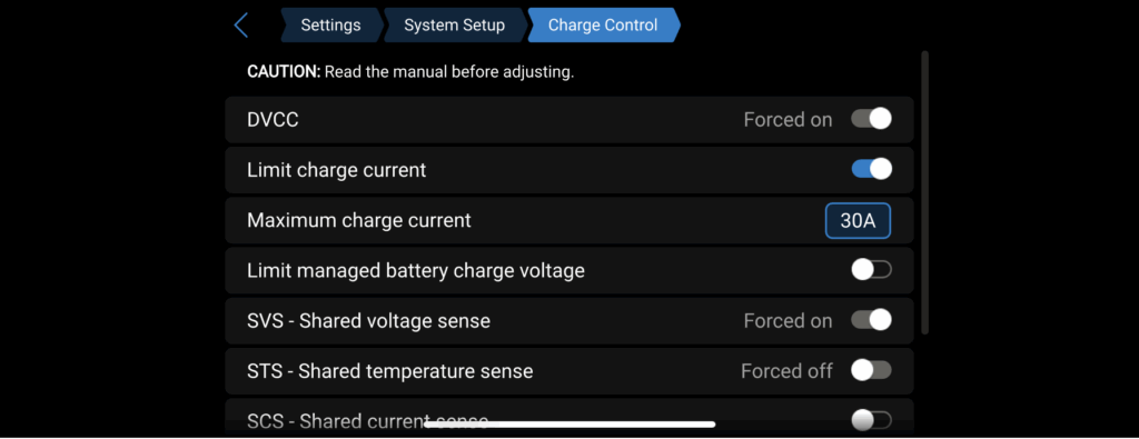
If you have a cerbo you need to decide if you want to enable Distributed Voltage and Current Control (DVCC). This comes into play if you have multiple charge sources and want to control them through a single interface. Once I added two Orion XS 1400 DC-DC chargers and connected them to the cerbo, DVCC was forced on.
I normally leave maximum charge current set to 70A (same as Multiplus), unless I am actively controlling both Orions through this interface. The image below shows the charge current set to 30A—I was attempting to cool the alternators on a hot day.
Victron Remote Monitoring (VRM)
Once the Cerbo is configured and connected to the Internet, I recommend setting up a login to the VRM here. This is a free service that allows you to control and monitor your system from anywhere in the world. Sweet!
Final Photo Dump


Next Up
The next post represents a separate branch of this series where I cover changes made to charge from our truck’s dual alternators. In it I cover features of a new Victron product, the Orion XS 1400.
Parts List
Here is a list of items we purchased to build our system.
You can navigate the Excel spreadsheet below directly or download the file through the download button on the bottom right.
We are Amazon affiliates and appreciate your purchases through the provided links.
We are also Tnutz affiliates. They offer the lowest prices on the web for aluminum extrusions, brackets, and much else. Before ordering through Tnutz check out this page to learn how to save on shipping.
Thank you!