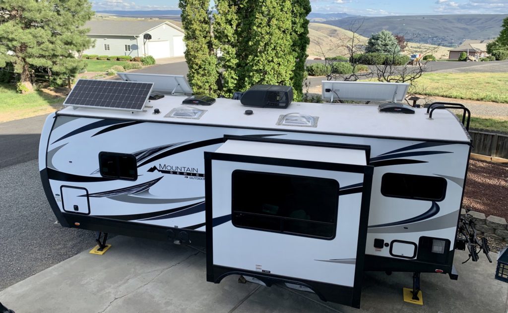
After the electrical upgrade on our Jayco Greyhawk motorhome was complete I did not expect another so soon. We planned to travel several years before the next major change. However, by the end of our 2019/2020 snowbird trip, we replaced the Greyhawk with a brand new 2020 24RKS ORV travel trailer. This project was an order of magnitude greater in complexity than the last since it included both an inverter and rooftop solar. Regardless, I thoroughly enjoyed the work that was necessary to pull this off. We now have a sweet system that will serve us well for years to come!

System Requirements
After selling our motorhome on the road, I wanted an electrical system that facilitated future sale without expensive components left behind. Hi-tech gadgets add little value, especially on trade-in. Why not keep them for the next RV? We didn’t do badly on the sale of the Greyhawk; we kept our lithium batteries and charger module. However, the battery monitor, many feet of 2/0 cable, and other electrical components went with the sale. Either it was too difficult or removal would have left visible holes in the cabin area.
- [Goal] Conversion back to a stock system should be as simple as possible.
- [Requirement] No visible modifications inside the cabin (i.e. for controllers, monitors, or outlets).
Another requirement was that it must have an inverter. An inverter is a device that converts direct current (DC) from your battery bank to alternating current (AC). This comes into play when shore or generator power is unavailable or undesired. Even though both TVs are DC, we wanted AC power for laptop computers and other devices. This was not an issue on the Greyhawk because it came equipped with a respectable 1000W Magnum inverter. However, this time around we wanted a bit more power. It would have been nice to run the instant pot, coffee pot, hair dryer, or microwave without firing up the generator. Also, I didn’t like running extension cords because the inverter was only available at two outlets.
The last requirement was that it must have rooftop solar. We did not bother on the Greyhawk because it wasn’t clear it was necessary. Between the onboard generator and portable Zamp 200W solar panel we did OK. Based on anticipated power needs and no onboard generator this time around, we thought the extra solar charging would be nice. And, there is a convenience factor with onboard solar, its ready to charge all the time—even while driving. Also, where theft is a concern we can keep our expensive portable panel locked away.
Choosing Major Components
Batteries
As mentioned previously, we kept our two lithium 100Ah Battleborn batteries we had installed in the Greyhawk. We recommend them for all the reasons discussed here. I felt two batteries were sufficient based on our months of use in the Greyhawk—and I didn’t want to spend $950 to buy another!
Battery Monitor
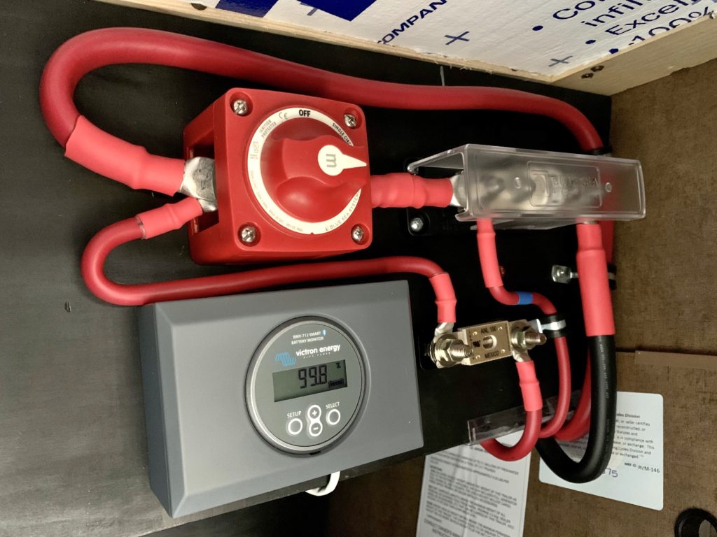
As discussed here, voltage is a poor indicator of State of Charge (SOC) for lithium because it varies little over the discharge cycle—a gauge that counts coulombs is needed. We purchased the same Victron BMV-712 battery monitor we used on the Greyhawk. I also purchased an optional temperature monitor cable to avoid charging when the batteries are too hot or cold.
Inverter
A good starting point when choosing an inverter is to determine how you plan to wire it into your system. This can be as simple removable clips attached to your battery bank with devices plugged directly in the inverter. You could opt for a hard-wired installation and provide power to a small number of dedicated AC outlets. Or, if you wish to provide power to all your existing outlets, you could plug the inverter into the shore power cable. For this option do not forget to disconnect the converter each time so it doesn’t act as a bank depleting load. One of these choices might be right for you depending on your situation. However, drawbacks associated with the above alternatives steered us to an inverter/charger.
An inverter/charger is a dedicated whole-house inverter that supplies power to every load in an RV. When shore power is available an inverter/charger acts as a pass-through for AC and charges the batteries, eliminating the need for a converter (AC to DC conversion). Otherwise, when shore power or a generator is not used it acts as an inverter and converts DC supplied by the batteries to AC. An important feature of this type of inverter is its built-in automatic transfer switch. This switch prevents backfeeding of the AC supplied from the batteries through the inverter to shore power or a generator—something to be avoided.
I felt an inverter/charger would be easier to install than a standard inverter to dedicated outlets. Wiring is straightforward. First, disconnect shore power from the main breaker and run a cable to connect shore power to inverter AC input. Next, connect inverter AC output back through another cable to the main breaker. It’s recommended to install a breaker between shore power and the inverter. Don’t forget to disconnect your converter because it is no longer needed.
The next decision was size in terms of wattage. This choice is less definitive, but there are a few things to consider that may help clarify. First, examine the wattage requirements of the items you wish to run. Which of these will be ran simultaneously? Will the inverter you are considering be sufficient?
Another important factor is the size of your battery bank and it’s ability to supply current to the inverter. The rule-of-thumb for inverters (not a hard-and-fast rule) is to divide size in watts of the inverter by 10 to get the full load input current at 12 volts. Our batteries are rated at 100A continuous each or 200A total. Rearranging, the rule suggests an inverter size of 10 * 200A = 2000W.
Finally, consider how your RV is wired with regard to AC Power, either 30A or 50A. If 30A the system is designed to be driven by 30A * 120V = 3600W. If 50A, there are two 120V legs, so this entire system requires 2 * (50A * 120V) = 12,000W. Our trailer is 30A, but we do not plan to run the air conditioner from the inverter, so we can subtract those 1800 running watts. For our case we are looking at an 3600W – 1800W = 1800W system. Regardless of the size you choose, with an RV you must be mindful of concurrent loads to avoid an overload and/or damage to components.
With inverter type and a rough size in mind, I was ready to choose a manufacturer and model. Initial front runners were the AIMS 2500W Inverter/Charger, model PICOGLF25W12V120AL and the Victron Multiplus Compact 2000VA Inverter/Charger. For price ($568) and power rating the AIMS was hard to beat. At 2500W continuous and 7500W max, we would not be running this inverter at it’s maximum, which can only lengthen it’s lifespan. While I liked the price, I kept coming back to the Victron. Reviews I read for the AIMS indicated while customer service is good, quality, reliability, and features do not measure up to Victron.
The configurability of the Victron is superior. While the AIMS is limited to a few hardware settings, the Victron has a full suite of software settings. While this adds complexity, it also means there is a good chance it can be configured to play well with other devices in your system.
Another cool feature of the Victron is it’s hybrid PowerAssist technology. As demand requires, the batteries provide an extra boost of power. This is done to prevent an overload of a limited source such as a generator or shore power. For example, if you are connected to 15A shore power and you start the air conditioner, you can avoid tripping the breaker when the inverter current limit is set to 13A. This also means you can save money since the size requirement of the generator you buy is less.
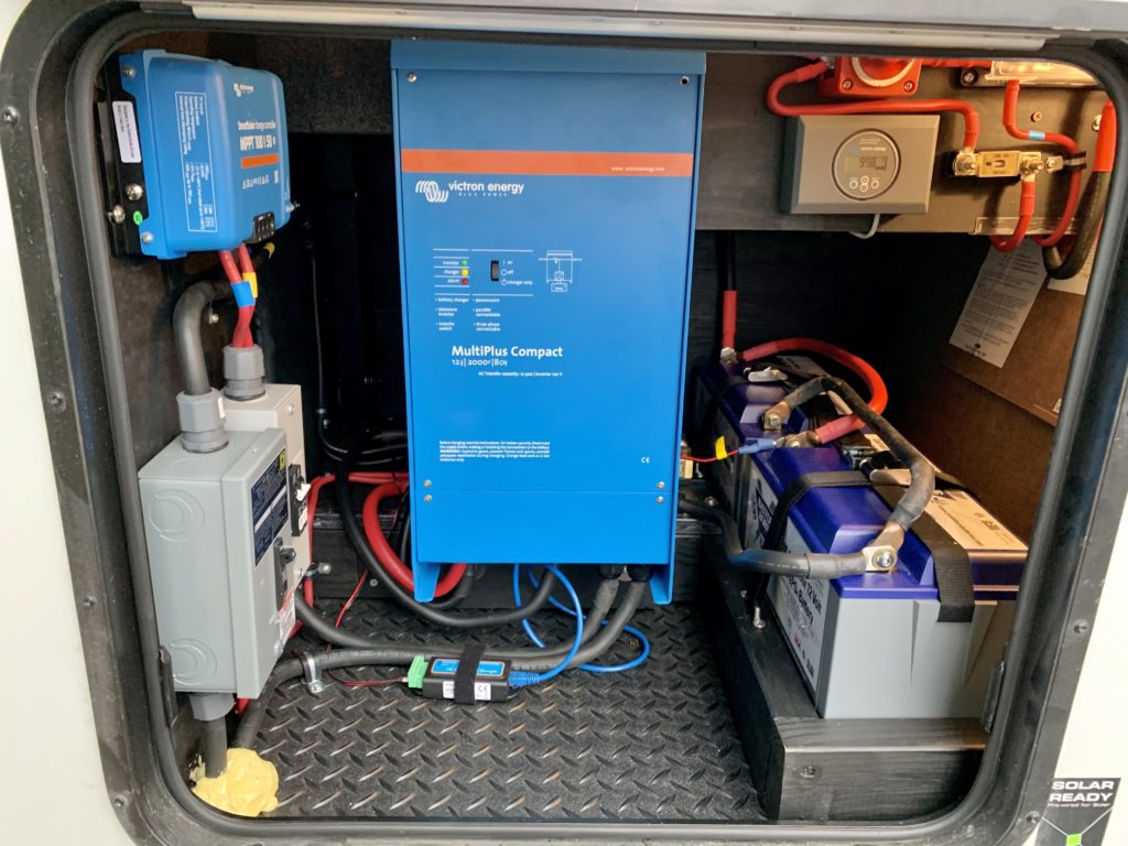
My favorite feature of Victron devices is their Bluetooth support. While the inverter does require purchase of a separate Bluetooth dongle, the battery monitor and charge controller have it built-in. Via wireless connection to a smartphone or tablet, the VictronConnect App makes control and monitoring simple and painless. This feature was key in meeting our requirement of no visible modifications inside the cabin.
Solar Panels and Charge Controller
After taking measurements of available space on the roof, it appeared it would accommodate three or four 200W panels. This time around I wanted at least double the charge capability we had with our portable 200W panel. Considering the fixed nature of rooftop panels—you can’t easily move them to follow the sun—I felt that three 200W panels would meet our needs.
To see the benefit of the MPPT charge controller we planned to buy, the controller requires a relatively high photovoltaic (PV) voltage, via panel cell count and/or series connected panels. Since we planned to buy three panels a series connection was not an option—high cell count was critical. Common sizes for a 12V system are 36, 60, or 72 cells. Based on available space and panel size, I went with 60 cell panels (NPA200S-24H) from NewPowa. These are marketed as 24V panels and are rated at 34Vmp and 40.46Voc.
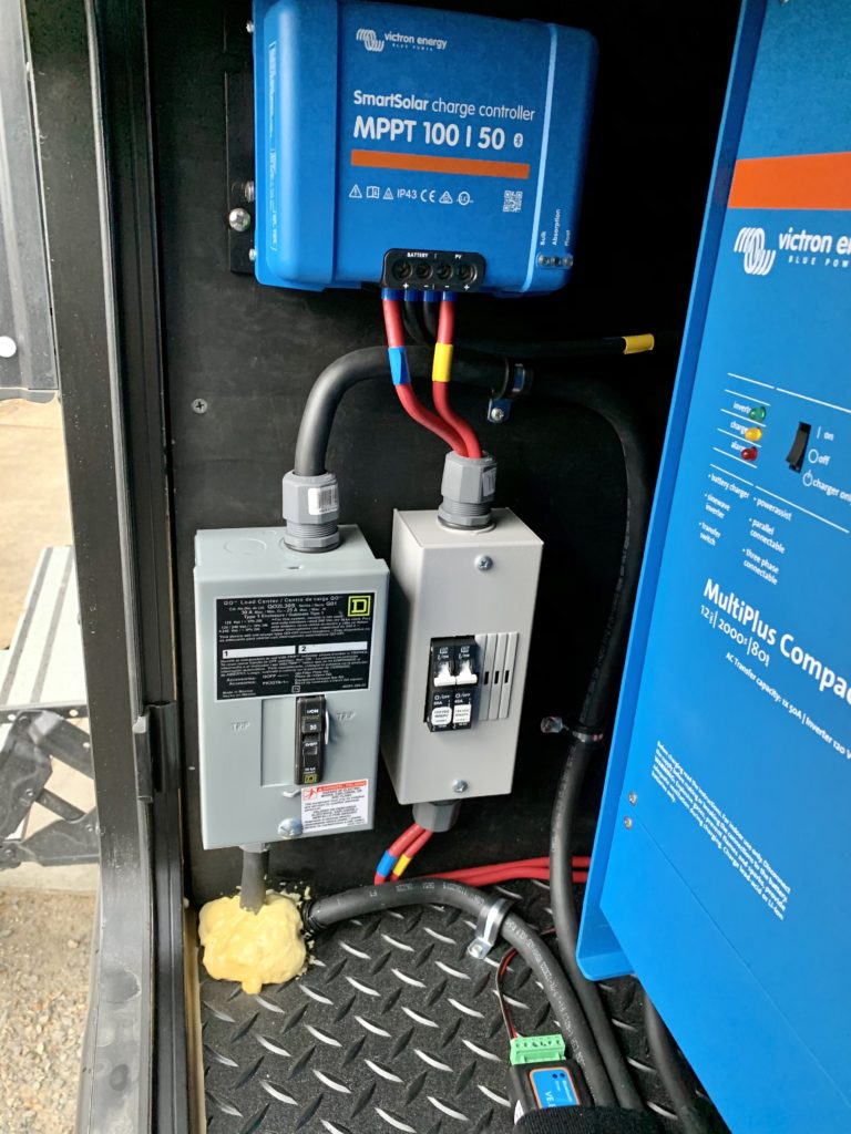
Decided on Victron components for both the inverter and battery monitor, it was a no-brainer to go the same route for the charge controller. I chose the Victron SmartSolar 100/50. This model is rated for 700W, which allows for a future upgrade to a fourth 200W panel for 800W total (slight overpaneling) and a 2S2P configuration. I don’t think this will be necessary.
Design
Diagrams help to ferret out issues early and provide a means to capture design decisions. I recommend Draw IO because it’s easy to use and free.
Electrical
The schematic below is a mix of components that were purchased for the upgrade and those pre-existing on the trailer.
For high current DC paths I chose 2/0 cable because it is rated to handle 200 amps for the lengths required, which is the maximum current my battery bank can source continuously. The catastrophic fuse is a 300 amp class T. These have an Amperage Interrupt Current (AIC) of nearly 20,000 amps and are incredibly fast acting when catastrophes (i.e. shorts) strike. Also, 300 amps is good size because it is within the rated ampacity of 2/0 cable, yet large enough to avoid nuisance blows of this expensive fuse.
Two bus bars are shown, one (red) positive and one (black) negative. The larger negative bus bar (650A) is connected to the chassis via 2/0 cable. It is connected in series with the battery monitor shunt and the negative terminal of the battery bank. All current that enters and leaves the bank is recorded by the shunt for high accuracy SOC measurement. The smaller positive bar (250A) is primarily a connection point for the positive load cables that had been connected to the stock battery bank.
Two subpanels were necessary. One holds the 30A breaker that is required between shore power and inverter AC input. The other is a Midnite Solar “baby box”, which controls and protects PV input and battery output of the solar charge controller, 40A and 60A breakers respectively.
The details of rooftop solar are not shown. The three solar panels purchased were connected in parallel through the existing Zamp Solar roof cap, with each panel protected by a 15A, 250V fuse. More on this later.
Mechanical
With electrical components chosen, I needed to figure out where and how I would install them. Leading options were under the bed or in the pass through storage; we went with the latter. Lusha wanted to keep space under the bed free for extra blankets and bedding, and I felt installation would require less time in and out of the trailer and on my knees, bending and reaching.
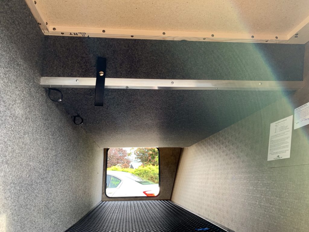
With component dimensions in hand, I took measurements inside the pass through. About 14″ inside the door compartment height drops from 28″ to 20″, where the bed runs across the space above. With inverter height also 20″ mounting options were limited. In the 20″ space the inverter would need to be mounted horizontally to provide its required 4″ spacing. Horizontal mounting is allowed, but for best cooling a vertical installation is recommended. I decided to mount vertically on a board centered in front of the door, adjacent to the main cutoff switch and battery monitor.
The other major decision was battery location. Placed side-to-side little space remains to get the inverter in and out of the compartment and allow access to battery terminals. For this reason I positioned them end-to-end. This battery layout sets a frame depth that allows for sufficient space between remaining components while minimizing wasted space.
Construction and Installation
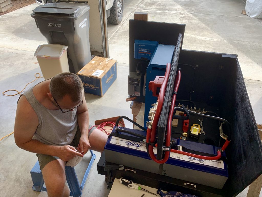
Next came the scary part—cutting wood, drilling holes, and assembling component boards. Other than some wavy rip cuts (I don’t own a table saw) it went pretty well. I used machine screws, tee nuts, threaded inserts, and carriage bolts to assemble mount boards and attach major components. The benefit of machine over wood screws for much of the assembly was huge. This facilitated disassembly/reassembly and made it possible to do the lion’s share of wiring, enter configuration settings, and perform system tests in my garage prior to trailer installation.
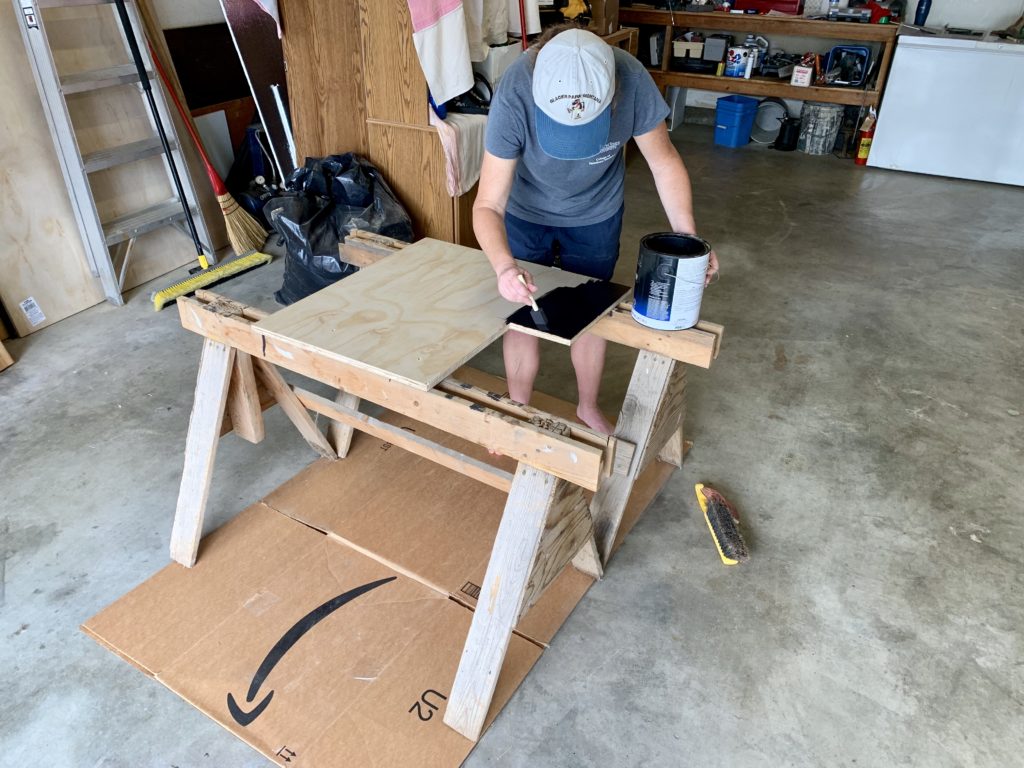
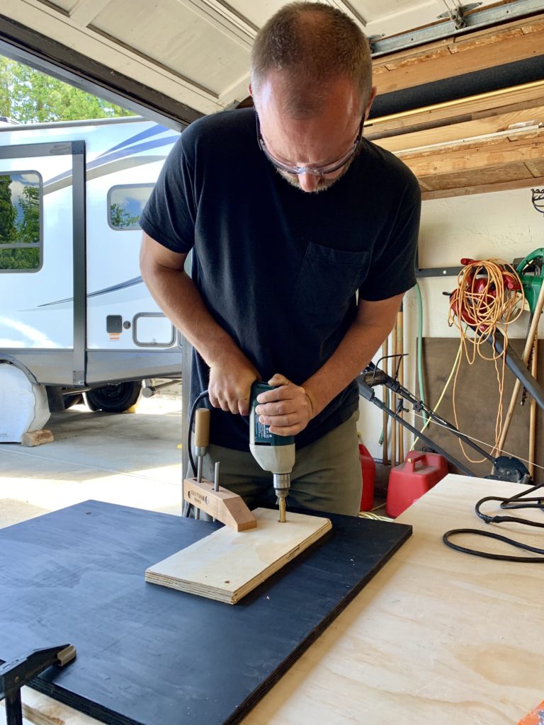
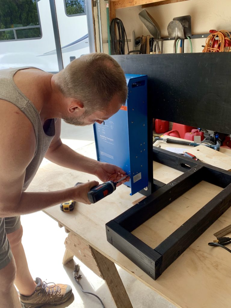
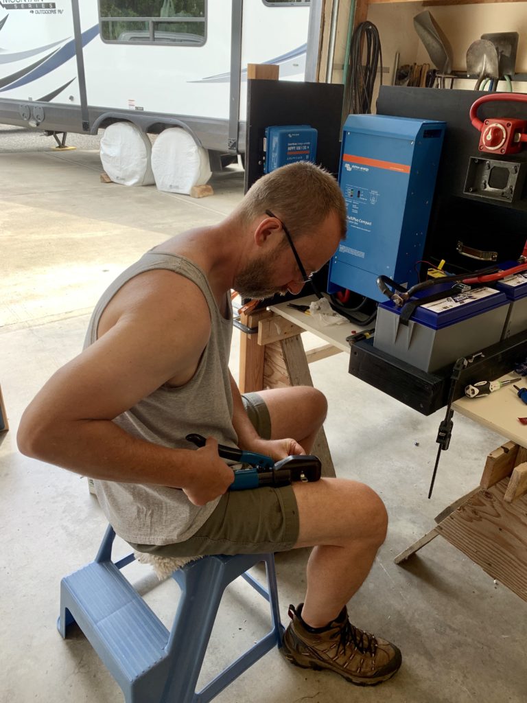
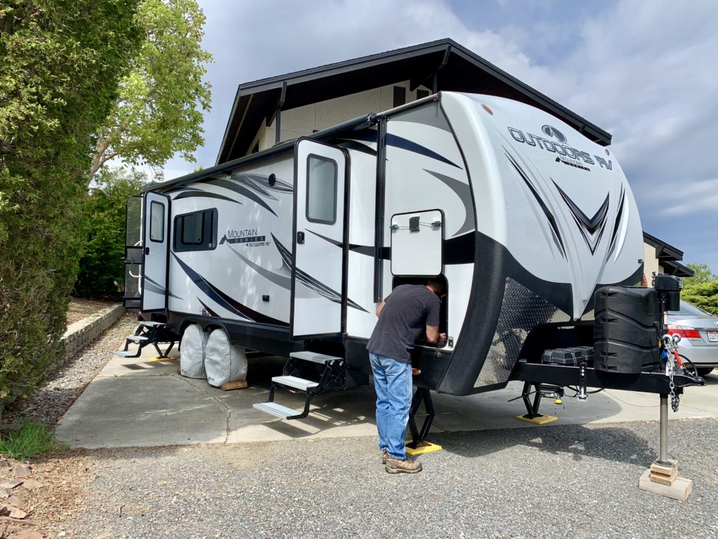
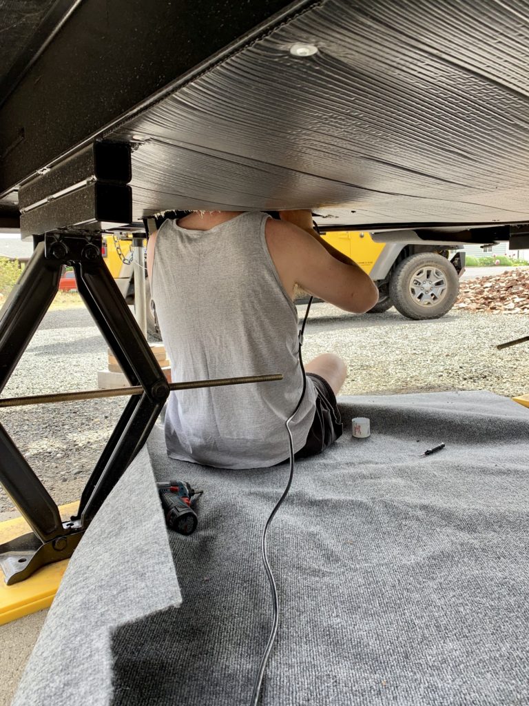
The task I was most concerned about was no big deal—where to drill holes and run cable in the trailer. When we picked up the trailer from Thompson RV in Pendleton I spoke with Mark, their lead technician. For DC cables, he recommended a hole in the junction area, centered in the pass through storage near the front cap. For AC cables, he recommended a hole adjacent to the pass through door, behind the front steps, up through insulation next to the low point drains (below the bedroom sink), through the wall into the power center.

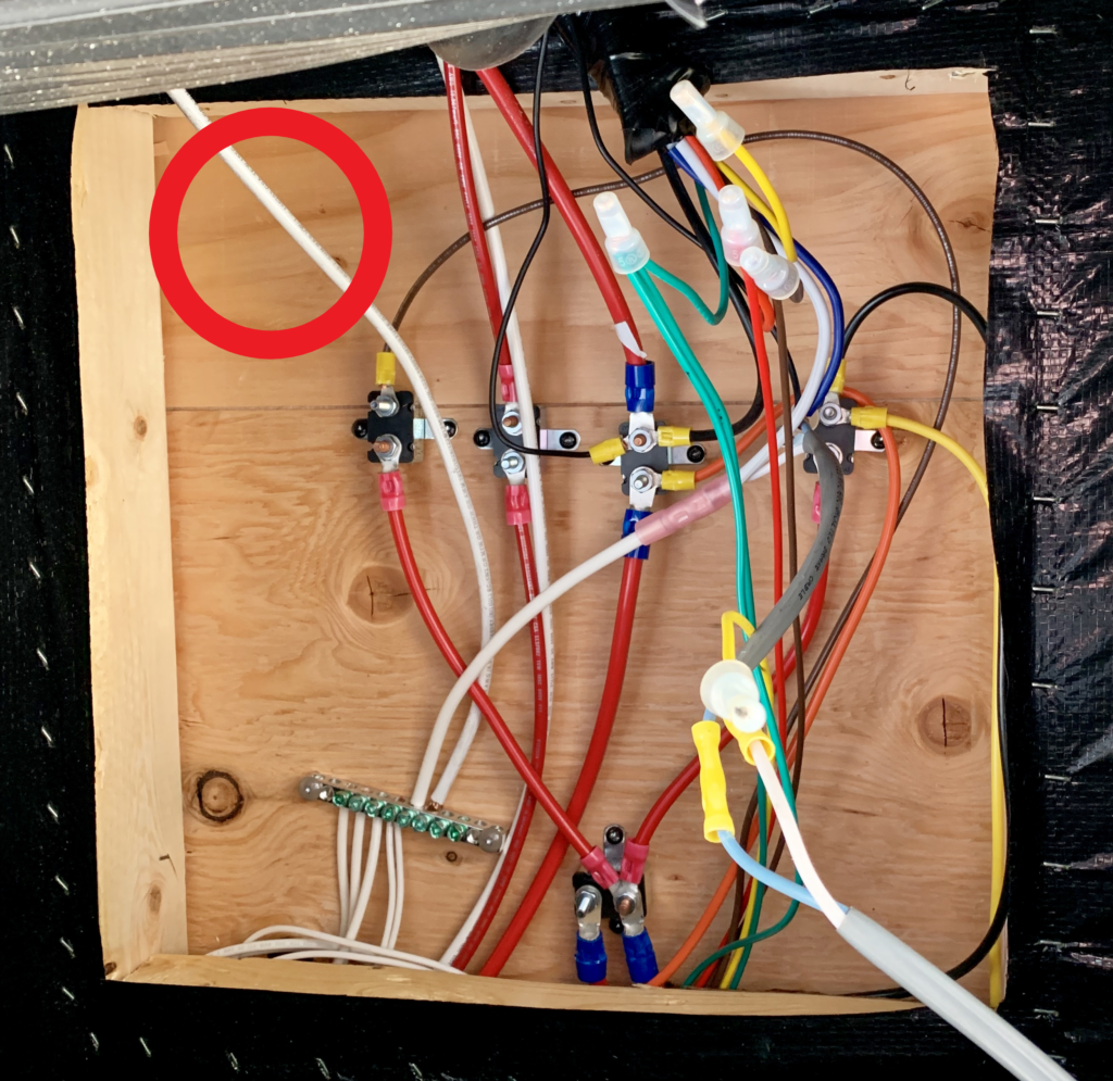
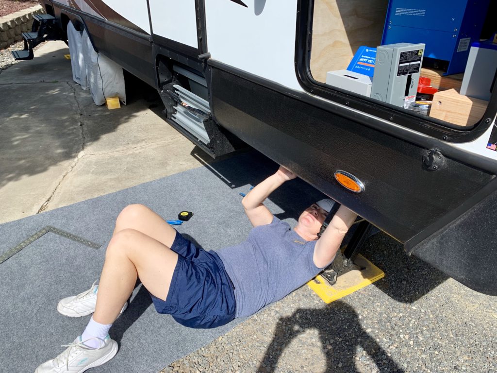
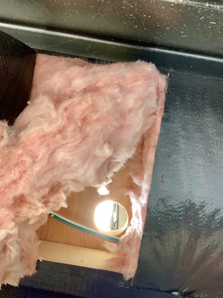
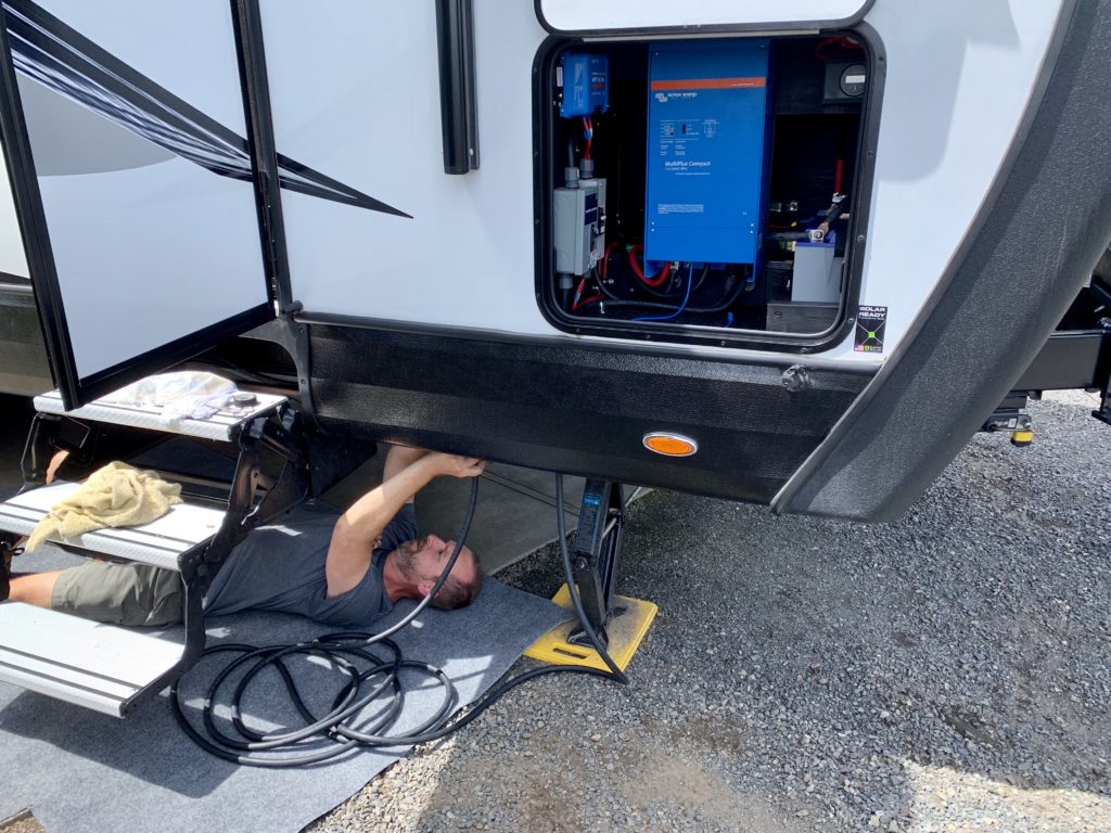
An important part of any electrical project is the quality of the connections. In addition to good crimper, I used Ideal Noalox Anti-Oxidant compound on all high current cable ends prior to crimping. I got the idea from this video by Ray at Love Your RV. Noalox literature says it promotes cooler operation and longer connection life, along with anti-seizing behavior, making it also a good choice for battery terminal and bus bar connections.
I also used two types of electrical connectors I hadn’t used before, ferrules and Wago nuts. Ferrules solve the problem of loose or brittle connections between screw terminals and stranded wire. These were used on solar charge controller, inverter, and breaker screw terminals. Wago nuts employ a snap lever and view window to ensure a solid connection. They are recommended in place of wire nuts for high vibration, stranded wire installations. These were used to make the AC to AC (10/3) cable connections. Note that Wago nuts do not work on ferrule ends, they only connect to bare wire.
Rooftop Solar
I ended up with what I believe is a fantastic solar mounting system. When we received our first set of mount brackets I was thoroughly disappointed. Their tilt design was asymmetrical; one direction they were even but the other the arm required bending. I also had concerns about the small surface area of the feet. How would these hold up to wind? I sent them back and bought these brackets recommended by my friend Tom. They have a solid tilt design and large mount surface.
It was unclear how to securely mount these flat brackets across my arched trailer roof. Then, I watched this video by Travel New Trails. He used strut channel in a length-wise installation to provide the large flush mount surface I sought. Strut channel simplifies panel removal/replacement since they are attached via movable strut cone nuts, not directly to the roof. Channel thickness (13/16″) adds additional spacing between roof and panel to minimize heating losses. They also provide makeshift cable raceways and attach points to secure cable that otherwise would not exist. I purchased three 10′ lengths of channel and cut each in half, which was perfect for my three 65″ long solar panels. I attached the strut channel to the roof with butyl tape and a mix of #10 stainless steel sheet metal screws and the self-tapping screws that came with the mounting brackets. I covered the screws with a heavy coat of self-leveling Dicor.

Our ORV travel trailer came pre-wired for rooftop solar. The components used for pre-wiring by other manufacturers can be pretty lousy, but that of ORV isn’t bad. They install a ZAMP ZS-3B-CAP roof cap that includes three parallel ports and run 8 AWG cable down the front cap to the batteries. The intention of this layout is to connect the charge controller above the bed. For my system, I spliced the wires above the bed together to run directly to my controller in the pass through storage. I also bypassed the 30A short stop overload in the front electrical junction since I installed my own breakers. All that remained was to butt splice solar cable, SAE connectors, watertight fuse holders, and install 15A fuses.
Parts List
This is not an exhaustive list of all purchased items. For example, fasteners are left out because that depends on your particular installation. Hope this information helps!
Note: I am not a solar expert or licensed electrician, use this information at your own risk. Research and plan your own system accordingly.
Disclosure: We are Amazon affiliates. We earn a small commission on items ordered when you access Amazon through our website. There is no additional cost to you and it helps us to maintain our website.
Very nice work Jason. I’m speaking of both the actual work and this write-up. Good job my friend.
Thanks Tom!
Jason,
Great job documenting your project.
A couple of questions: did you consider installing a fan to exhaust heat generated by the inverter and charge controller out of the storage space, are the solar panels permanently ‘tilted’, and how did you integrate the leads from the rear panel into the system?
Regards,
Steve
Ps – I will be ‘swallowing my anchor’ next month and have just bought a 25RDS and will be installing a system very similar to what you have, so your write up is a great smell check for my thoughts!
Thanks Steve! Yes, I did consider installing a fan because the inverter can heat up when it’s hot out and you are running lots of current through it. I decided to buy a portable 10″ fan that runs off of 12VDC instead. It fits well in the compartment in front of the inverter. I can connect it through a round DC plug to the batteries with clips. There is also a 3/4″ gap around the rear access panel on top and on one side. Air can also flow a little by opening the opposite pass through door. I don’t think I’ll need the fan that often because we tend to stay in areas 70 degrees or less.
No, the solar panels are not always tilted. They have removable brackets that allow multiple tilt positions in both directions.
Not sure about the last question “how did you integrate the leads from the rear panel into the system”. Are you referring to the power center with the 30A main breaker?
Sorry I was not clear with the last question – wanted to know how you ran the wires from the aft panel to the charge controller.
What you are referring to as aft panel I call front (fore) since that’s how the owners manual does it. The front of the RV is adjacent to the tongue. I understand the confusion, when we are inside the trailer it seems like the bed is in the rear. I moved the red (+) solar cable attached to the 30A short stop overload in the electrical junction to stack it on the same post as the input, bypassing this overload. I extended this red 8 AWG cable with a butt splice to red 6 AWG cable to attach to the bottom of the 40A solar breaker in the baby box subpanel, and ran another red 6 AWG cable from the top of the breaker to the +PV charge controller input. I extended the white (-) solar cable with a butt splice to black 6 AWG cable to attach to the -PV charge controller input.
Bravo! A techno-rich post that was very much appreciated & enjoyed by this tech-geek. All those Physics classes came flooding back to me. You have the thought processes of a scientist. Best of all, the entire electrical system fits & performs purrfectly. Well done, my friend!
Thank you for the wonderful compliments and encouragement!
Jason,
Ok, third time is the charm!
How did you route the wires from the panel installed at the back of the trailer? In other words, do they run along the top of the roof to the factory installed ‘junction box’ at the front of the roof, or did you install another box and penetrate the roof near the panel?
Regards
I used the factory Zamp 3-Port Roof cap that was already installed on the trailer, no other roof access points were needed. I ran solar cable along the roof from the rear panel to the roof cap in the front. For the rear panel, I secured the solar cable with wire ties to the solar panel tilt brackets, both on the rear panel bracket and the front panel bracket near the roof cap. That is one of the nice features of mounting strut channel to the roof, it raises the mounting brackets off the roof a bit (13/16″), providing tie in points for wire ties through the bracket holes.
Wow Jason! I knew you had put a lot of work in this system upgrade but when you lay it out what all you had to do and why, it really blows my mind! Looks like a lot of research was done. Good job!!!
Thanks Diane! I learned from Dave on the Greyhawk electrical upgrade what it takes to make a project like this a success.
Jason,
We have finally moved from our boat to our new to us 2018 ORV 25RDS and now it is time to finalize the solar install. While climbing around the roof measuring for available panel mounting area yesterday, I noticed that the Zamp triple port roof cap states on the outside of the cowling that it has a max rating of 450w. Did that cause you any angst?
Regards
Hi Steve! It sounds like you have the older solar roof cap that has a lower rated thermal overload (Bussmann, part number 121A40-A2P0) built-in, which was intended for lower voltage 36-cell solar panels. That overload is technically underrated (12 VDC) for it’s intended use since charging happens at a PV voltage of 18 volts or more. Our 2020 ORV came equipped with the newer Zamp roof cap ZS-3B-CAP, which has no overload protection built-in. It simply has three ports wired in parallel with 10 gauge wire. So no, I felt good about using my roof cap, but you might want to consider swapping yours out with a different one.
Thx for the info.
Thank you for all the details. I have an Arctic Fox 25Y that is wired very similar to your ORV. When you brought your DC positive and negative cables into the pass through from the DC junction did you keep all the existing connections and fuses in the DC junction? Also, after drilling for the AC cables to your power center did you run the cables inside the trailer or outside on the underside of the TT. Thank you.
Hi Rick.
On the DC side, I bypassed the roof top solar 30A overload in the DC junction area, since I have differently sized breakers for solar in the baby box panel I installed. For that case I moved the red solar cable to the other side of the 30A overload to bypass it. I extended that cable with a butt splice and ran it to the solar controller. I ran the rest of the load side cables to the associated bus bars and extended with butt splices as needed.
For the AC cabling, I ran that outside the trailer, through a hole I drilled near the pass through door, behind the steps, up throw the insulation adjacent to the low point drains, and through a hole into the power center. I used Great Stuff spray in foam to fill in the holes.
Jason, thank you for your generous support. I greatly appreciate your advice. I have all of the parts ordered and will be taking on this project next month. Mentally I believe I’m about 90% there. If you don’t mind I may reach out to you when I get started on the project for further advise. All the best and travel safe.
Hi Rick,
Jason’s wife Lusha here. I’m so glad Jason could be of help. Best of luck to you with the upgrade of your Fox! Jason is happy to provide further advise- don’t hesitate to reach out. We have some travels coming up that will have us in and out of internet/cell range, so please forgive us if responses take a few days 🙂
Happy trails,
Lusha
Hi Lusha and Jason. How’s your 2021 Spring adventures going? I know when you started your Spring adventure the weather was a bit on the cool side. Knowing your lithium batteries are in the passthrough I was curious as to how they performed (charge) durning the colder weather.
Thank you,
Rick
Hi Rick. The adventure is going well! Cold weather is no issue since the passthrough is so well insulated. The compartment tends to be about 20 degrees warmer in the morning than the outside temp. This morning it was 33 degrees outside and the battery terminal temp was 57 degrees.
Thank you. Travel safe.
Wow I came across your website because I am planning on Buying this exact same model trailer myself! I have already done a ton of research and acquired numerous photos. Impressive setup as I was looking at adding solar myself after purchase. With the detailed photos you provided of the roof and mounts it allows me to plan and price my system. I was looking at placing my system under the bed as Matt and Diana from Adventurous Way did in their Outdoors RV. I might have to reconsider my placement but I was planning on using 3 or possibly 4 batteries because I need the AC where I am planning on going. Thank you.
Congratulations on your upcoming purchase! We love our 24RKS- in fact, I just posted a one year review here on the blog that you might be interested in. Jason’s electrical upgrade has performed really well and he’s even had some nice compliments from professionals who have stopped to admire his work. It certainly took a great RV and made it even better. I hope you don’t have to wait too long to get your new toy 🙂
Happy trails,
Lusha
Jason:
I am planning a similar electrical upgrade to my ORV Blackstone 240RKSB and was hoping you could share a bit more detail with me about wiring the AC lines from the shore power connector to your inverter/charger. I want to run a 6/4 wire from my front A-frame to the rear of the trailer and am wonder how you managed it. Thanks for the great post and any help you can offer.
Kelly, My AC line wiring was straightforward (see my electrical schematic). I ran a 10/3 cable from the AC input of the inverter to the 30A breaker in the sub panel I installed. I ran another 10/3 cable from the sub panel back to the RV power center. I disconnected the shore power cable from the power center and connected the shore power cable to my 10/3 cable. I ran another 10/3 cable from the AC output of the inverter back to the power center, and connected that cable where shore power had been connected.
The trickier part you are likely concerned about is where to run the cables. It was helpful to speak with a technician at the dealership about this. They recommended not removing the protective covering (looks like black cardboard) under the RV if possible, because he said it’s a pain to get back on. They recommended a hole adjacent to the pass through door, behind the front steps along the frame, up through insulation next to the low point drains (below the bedroom sink), through the sink cabinet wall into the power center. So, that’s what I did. Hope this helps!
Jason:
Thank you for your quick and helpful response. After looking at the 3D virtual walkthrough of your model it is clear how you ran the wires. Having the power center just aft of the bedroom sink was/is very convenient.
Unfortunately in our Blackstone 240 RKSB the power station is directly under where your refrigerator is, a much longer run. I’ll figure it out.
Jason, Your work and write-up are great, thanks for sharing. Your work has convinced me to abandon my idea of doing what limited work I could have done on the a-frame and use some of my pass-through space to do much more. I currently have three 200 W panels on my roof and a Victron 100/50 solar charger in the upper bedroom cupboard over the bed where ORV conveniently brought together PV cables from the roof port and battery cables up through the front trailer cap. However, now I want to add a 4th panel, route the PV cables to the pass-through space, and move the solar charger closer to the batteries, future inverter charger, etc. Did you need to route cables through the front cap of the trailer? I would simply use the existing battery cables as the new and longer PV cables, but it appears that ORV only took the positive battery cable down through the cap and tied the negative cable to the chassis somewhere beyond my view. Any experience in this area?
Hello Kelly,
A quick note to let you know we are in an area with very limited internet right now. We’ll be back in business in a couple weeks and Jason will be able to respond to your question. I apologize for the delay!
Lusha
Hi Kelly, No, I didn’t need to route additional wires through the front cap. The pre-wired 8 AWG solar cables, red (+) and white (-), ran from the bedroom cupboard down to the batteries. For my install I spliced those cables in the cupboard to the black/blue cables ran from the roof. I also bypassed the 30A short stop overload in the junction area under the RV that the red cable was connected to. This was necessary because I have my own breaker for the charge controller PV input in the baby box I installed. Hope this helps.
Hi Jason,
I just stumbled across your website while doing research for an electrical upgrade to my 2019 ORV 24RLS travel trailer. Your in-depth article on the install was very impressive. I just have a question on the AC cables you ran to the main panel. The main panel location in our trailer is almost identical to yours but in your article it wasn’t clear to me on the actual path that was taken. Do you have any other info/pictures showing how you ran the AC cables?
Thanks,
Todd Churko
Spruce Grove, Alberta, Canada
Todd,
I’m glad the article was helpful! Regarding your AC cable question, I don’t have anything to add to my earlier responses to the same question.
Thanks for the quick reply Jason,
I should have read through the other comments more thoroughly. The reply to Kelly is most helpful. Take care.
Glad you found it helpful Todd. This electrical system has been fantastic for dry camping. The wife (that’s me!) definitely appreciates it! Best of luck with your system. Hope to see you on the road.
Lusha
Hi Jason,
Another thank you here for such a great and detailed set of information!
I just purchased an ORV 24RKS and will be installing an inverter/charger/transfer-switch. The Victron unit you have is at the top of the list, however I’ve read the fan noise can be very loud on these, and am a bit concerned about installing it just on the other side of the cargo wall from the bed.
What is your experience with the inverter/charger’s fan noise?
Thank you!
Lance
The problem of sleeping right over the top of the inverter is more transformer hum than fan noise, and is only a problem if you are connected to shore power. It hums on a regular interval and lasts for ~20 seconds, even if the battery bank is fully charged. It didn’t bother me, but I’m a heavier sleeper and I was not the one right over the top of it. The solution for us is to ensure the inverter is in “Pass Thru” mode before bed. We do this by setting the inverter to “Charger Only” and setting the current limit to it’s minimum value. We were able to do this on our phones because we have the inverter connected to the Bluetooth dongle. You know you have it configured correctly if you see “Pass Thru” displayed for the inverter on your phone. There are fancier options for control and monitoring (Color Control GX, Cerbo GX, Raspberry PI with Venus OS), but we went cheap this go around. I just leave the inverter on Pass Thru anytime we are connected to shore power, because our solar charging is sufficient to keep up with DC loads, and AC loads are shore powered. Hope this helps!
Hi Lance,
Lusha here. Just to add to what Jason is saying, I sleep right over the inverter and was the one to notice the hum. It doesn’t do it very often, and it really isn’t that noticeable unless I’m right over it and all is quiet, but I’m a light sleeper and any little thing like that wakes me up. As long as Jason configures things the way he described, I have no problem. Good luck on your set up and with your 24RKS. It has been a great floor plan for us.
Happy trails,
Lusha
Another few questions about running the 120V cable to/from the trailer’s fuse/breaker panel to the inverter:
I saw you mentioned 10/3 for the gauge – what type did you use? Was it rated for outdoors?
Did you run the cable through conduit? If so, what type/size conduit?
Thanks!
Lance
I used this SOOW cable through this 3/4″ split loom where it runs outside the trailer.
Thanks Jason!